
Related Manuals for CSI IF10-S2


Summary of Contents for CSI IF10-S2
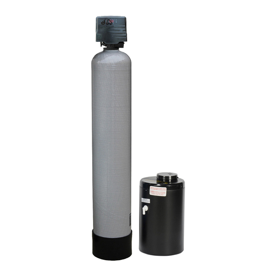
- Page 1 SIGNATURE 2 SERIES Greensand Plus Iron Filter Manual Installation / Operation Manual...
-
Page 2: Table Of Contents
SIGNATURE 2 SERIES Filter Specifications........................Page 2 Installation...........................Page 3 Control Start-Up Procedures.......................Page 8 Utilizing Bluetooth........................Page 11 Master Programming........................Page 12 Powerhead Assembly........................Page 13 Valve Body Assembly........................Page 14 Bypass Assembly.........................Page 15 Additional Information........................Page 16 Troubleshooting...........................Page 20 Error Codes..........................Page 20... -
Page 3: Filter Specifications
SIGNATURE 2 SERIES Specifications General Specifications IF10-S2 IF15-S2 IF20-S2 IF25-S2 Filter Media Greensand Plus ™ Filter Media Capacity (cu ft) 1.00 1.50 2.00 2.50 Garnet Sand Underbed (lbs) Mineral Tank (Vortech ™) 9 x 48 10 x 54 12 x 52... -
Page 4: Installation
SIGNATURE 2 SERIES Installation Greensand Plus Iron Filter is capable of removing dissolved iron, manganese and hydrogen sulfide from water through oxidation and filtration. The maximum practical limit of iron (Fe) and / manganese (Mn) in raw water is 10 ppm. The maximum practical limit of hydrogen sulfide (h2S) is 3ppm. -
Page 5: Installation Requirements
SIGNATURE 2 SERIES Installation GREENSAND PLUS FILTER (Incoming Water from Left-Side) HARD WATER TO OUTSIDE FAUCETS SERVICE GROUNDED & UNSWITCHED 115- VOLT OUTLET HOT SOFT WATER CITY WATER COLD SOFT WATER INLET WATER METER PRESSURE RELIEF VALVE (To drain) GREEN- SOFTENER SAND PLUS... - Page 6 SIGNATURE 2 SERIES Installation -Filter Location / Other Requirements- • Locate the unit near an unswitched, 120 volt / 60 Hz grounded electrical outlet. • Check for distance and proper drain installation (e.g. floor drain, washing machine standpipe). • Determine type and size of piping required for softener connection (e.g. copper, galvanized, PVC plastic). Note: Where the drain line is elevated above the control valve or exceeds 20 feet in length to reach the drain, use 3/4”...
- Page 7 SIGNATURE 2 SERIES Installation -Drain Line Connection- 1. Pull out clip and remove drain line assembly located on the left side of control valve. Remove drain line hose barb and wrap threads with Teflon tape. Reinstall drain line hose barb. Caution: Hand tighten only!! Replace drain line assembly and reinstall clip.
- Page 8 SIGNATURE 2 SERIES Installation Electronic Connections P - Power Supply B - Powered in Backwash Cycle Only S - Powered in Entire Regeneration Cycle - Electrical Connection - 1. Connect the power supply to the control valve and plug into a 115 volt / 60 Hz receptacle. Note: Do not plug into an outlet controlled by a wall switch or pull chain that could inadvertently be turned off.
-
Page 9: Control Start-Up Procedures
SIGNATURE 2 SERIES Control Start-Up Procedures - Final Checkout - 1. Be certain that the bypass valve is in Service position and main valve is completely on. 2. Check electrical supply to be certain the cord is connected to an uninterrupted 115 volt outlet. 3. -
Page 10: Normal Operation
SIGNATURE 2 SERIES Control Start-Up Procedures Normal Operation Home Display a. Alternates between the display of Time of Day and Number of Days until the Next Backwash. (Metered Softeners will alternate between time of days and gallons remaining until next regeneration) - Days Remaining until the Next Backwash will count down from the entered value until it reaches 1 day remaining. - Page 11 SIGNATURE 2 SERIES Control Start-Up Procedures Starting Extra Regeneration Cycle To Start Delayed Extra Cycle Example ( 1 ) If Days Remaining Until Next Backwash does not read ‘1’, press and hold the Set/Change button for 3 seconds until the display reads ‘1’. Backwash cycle will initiate at the next designated backwash time.
-
Page 12: Utilizing Bluetooth
SIGNATURE 2 SERIES Utilizing Bluetooth Control To take advantage of the Bluetooth interface this feature must be set up on a Bluetooth enabled device. Note: At the time of this release Bluetooth control only works on Android devices with a compatible version of Bluetooth. -
Page 13: Master Programming
SIGNATURE 2 SERIES Master Programming Mode Master Programming Mode To enter Master Programming Mode, press and hold both buttons for 5 seconds. Note: All Master Programming functions have been preset at the factory. Unless a change is desired, it is NOT necessary to enter Master Programming Mode. 1. -
Page 14: Powerhead Assembly
SIGNATURE 2 SERIES Control Valve Powerhead Assembly LETTERS IN DIAGRAM REPRESENT WIRING CONNECTIONS * "F" Port is for softener flow meter connection (flow meter not shown) Description Part Number Timered Power Head Assy. 21001X100 Metered Power Head Assy. 21003X100 Softener Circuit Boad Assy. 21001X102 Encoder 20001X124... -
Page 15: Valve Body Assembly
SIGNATURE 2 SERIES Valve Body Drive Assy. Description Part # Qty. R e f Piston Assembly 20001X231 10-24 x 13/16 Screw 20001X226 Seal & Spacer Kit 20561X253 End Spacer Flow Control Button 1.5 GPM 20251X266 Flow Control Button 2.0 GPM 20251X267 Flow Control Button 2.4 GPM 20251X268... -
Page 16: Bypass Assembly
SIGNATURE 2 SERIES Bypass Assembly Ref # Description Part # Plastic Bypass Valve Assembly 20561X292 Bypass Valve 3/4” Stainless Steel 20561X270 Bypass Valve 1” Stainless Steel 20561X283... -
Page 17: Additional Information
Service Instructions / Instructional Videos Service Instructions / Instructional Videos SIGNATURE 2 SERIES Available at www.csiwater.com Available at www.csiwater.com General Preliminary Instructions PERFORM BEFORE ALL SERVICING OPERATIONS 1. Turn off water supply to conditioner. -If the conditioner installation has a “three valve” bypass system, first open the valve in the bypass line, then close the valves at the conditioner inlet and outlet. - Page 18 Service Instructions / Instructional Videos SIGNATURE 2 SERIES Available at www.csiwater.com To Replace Brine Valve 1. Follow steps A1 - A3 2. Remove the control valve cover. Disconnect the meter cable from the meter assembly. 3. Remove screw and washer at piston drive yoke. Remove powerhead mounting screws.
- Page 19 Service Instructions / Instructional Videos SIGNATURE 2 SERIES Available at www.csiwater.com To Replace Seals and Spacers 1. Follow steps A1 - A3. 2. Remove the control valve cover. Disconnect the meter signal wire from the meter. 3. Remove screw and washer at piston drive yoke. Remove powerhead mounting screws. The entire powerhead assembly will now lift off easily.
-
Page 20: Troubleshooting Guide
SIGNATURE 2 SERIES Troubleshooting Guide SYMPTOM PROBABLE CAUSE CORRECTION Power supply plugged into Connect to constant power source intermittentent or dead power source 1.Softener Fails to Disconnected meter cable Reconnect cable Regenerate Improper control valve Reset program settings programming Automatically Defective power supply Replace power supply Meter is dirty or defective... -
Page 21: Troubleshooting
SIGNATURE 2 SERIES Troubleshooting Guide SYMPTOM PROBABLE CAUSE CORRECTION Plugged drain line or drain line control Check flow to drain. Clean drainline flow control button 7. Excessive Water in Dirty or damaged brine valve Clean or replace brine valve. Brine Tank and / or Plugged injector or screen Clean or replace injector screen. - Page 22 SIGNATURE 2 SERIES...
- Page 23 SIGNATURE 2 SERIES Notes:...
- Page 24 SIGNATURE 2 SERIES 710 Orange Street, Ashland, OH 44805 PH 419.289.1500 FAX 419.289.1515 www.watersoftinc.com...
Need help?
Do you have a question about the IF10-S2 and is the answer not in the manual?
Questions and answers