Table of Contents
Advertisement
Quick Links
Installation AND OPERATION INSTRUCTIONS
IF YOU CANNOT READ OR UNDERSTAND THESE INSTALLATION INSTRUCTIONS DO
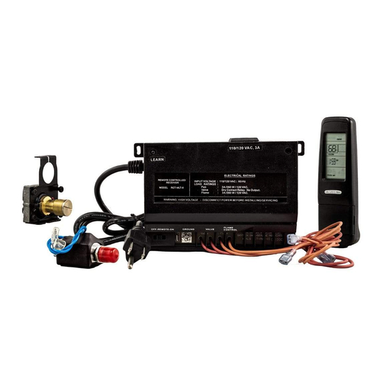
INTRODUCTION
This remote control system was developed to provide safe, reliable, user-friendly remote control system for gas heating appliances. The
system can be operated manually from the transmitter and is designed for use with an SIT gas valve.
TRANSMITTER
+
FAN
FLAME
-
LIQUID CRYSTAL DISPLAY - LCD
1.
Low Battery Indicator - Battery power is low, replace batteries within two weeks.
2.
Timer - Time remaining before the system shuts off, must be programmed.
3.
Mode - Indicates whether the system is ON, OFF, or in THERMO mode.
4.
Set - Indicates the desired SET temperature when in THERMO mode.
5.
Flame - Indicates burner/valve operational and flame height.
6.
Clock - Indicates current time.
7.
Room - Indicates current ROOM temperature.
8.
ºF - Indicates degrees Fahrenheit (ºC indicates degrees Celsius).
9.
Fan - Indicates the fan is ON, or is programmed to come ON.
MODE FUNCTION
To select an operational mode, press the MODE button on the transmitter.
ON - Turns the appliance ON, the flame icon will appear on the LCD screen.
THERMO - Remote is in THERMO mode.
OFF - Turns the appliance OFF, the flame icon will disappear from the LCD screen.
SETTING ºFAHRENHEIT / ºCELSIUS SCALE
The factory setting for temperature is degrees fahrenheit (ºF). To change this
setting to degrees Centigrade (ºC):
•
Remove battery cover on the back of the transmitter and locate the setting
button in the top center of the battery compartment.
•
Push the button once to enter temperature display setting mode.
•
Use the up and down buttons to switch between the ºF and ºC.
•
Push the setting button again once again to set the displayed temperature
scale.
•
Repeat this procedure to switch back to ºF.
THERMOSTAT FUNCTION
•
Press the MODE key until the LCD screen shows the word "THERMO" at the top of the screen.
•
To adjust set temperature, press the UP and DOWN buttons until the desired temperature is reached. The temperature range is
99ºF (37ºC) to 45ºF (7ºC).
•
If no button is pressed, the set temperature will automatically be accepted.
•
The flame icon will appear when the control calls for heat. The flame icon will disappear when the appliance reaches its set
temperature.
•
Press the MODE key to disengage the Thermo Mode.
Skytech: RCTS-MLT-IV
MODEL: RCTS-MLT-IV
NOT ATTEMPT TO INSTALL OR OPERATE
The transmitter operates on (2) AAA 1.5V batteries that are included. Install the AAA
batteries supplied with the unit into the battery compartment. It is recommended that
ALKALINE batteries always be used for this product. Be sure the batteries are
-
installed with the (+) and (-) ends facing the correct direction.
If the transmitter does not illuminate when you press any buttons, or you see nothing on
+
the LCD screen, check the position of the batteries, and if they are fully charged.
E474962
ON
3
THERMO
X
OFF
7
E
E
SET
ROOM
AM
6
PM
TIMER
TIMER
HI
9
MED
LOW
FLAME
LA
AME
FAN
OFF
SETTING
BUTTON
-
+
+
-
REV. 3-19-20 Page 1
1
4
8
2
5
Advertisement
Table of Contents

Subscribe to Our Youtube Channel
Related Manuals for Skytech RCTS-MLT-IV


Summary of Contents for Skytech RCTS-MLT-IV
- Page 1 MODEL: RCTS-MLT-IV INSTALLATION AND OPERATION INSTRUCTIONS IF YOU CANNOT READ OR UNDERSTAND THESE INSTALLATION INSTRUCTIONS DO NOT ATTEMPT TO INSTALL OR OPERATE INTRODUCTION This remote control system was developed to provide safe, reliable, user-friendly remote control system for gas heating appliances. The system can be operated manually from the transmitter and is designed for use with an SIT gas valve.
- Page 2 If an Adult is going to be away from the hearth appliance or fire feature for any length of time, then the handheld/wall mount, receiver/control module and application should be in the “OFF” position. Skytech: RCTS-MLT-IV REV. 3-19-20 Page 2...
- Page 3 Electronic Module, and connect them to the receiver wires using the spade connectors. NOTE: An adapter may be necessary to make the connection between the OUTLET Electronic Module and the Remote Piggyback Connectors Receiver. Electronic Module Switch Wires REMOTE RECEIVER Skytech: RCTS-MLT-IV REV. 3-19-20 Page 3...
- Page 4 (on the receiver). (See Figure 3) CAUTION TO ENSURE SAFE OPERATION, THE OUTLET PRESSURES ON BOTH REGULAR AND HI FLAME LEVELS SHOULD BE CHECKED WITH A MANOMETER IN ACCORDANCE WITH SPECIFICATIONS SUPPLIED BY THE VALVE MANUFACTURER. Skytech: RCTS-MLT-IV REV. 3-19-20 Page 4...
- Page 5 “CP” will appear on the LCD screen if any button is pressed while childproof mode is engaged. • When this mode is engaged, all auto settings go on without interruption (like thermostat). Only manual functions are prevented. Skytech: RCTS-MLT-IV REV. 3-19-20 Page 5...
- Page 6 If receiver is installed in a tightly enclosed metal surrounding, the operating distance will be shortened. • Make sure the hand-held transmitter and remote receiver are communicating properly (see LEARNING TRANSMITTER TO RECEIVER section). Skytech: RCTS-MLT-IV REV. 3-19-20 Page 6...
- Page 7 U.S. INQUIRIES CANADIAN INQUIRIES SERVICE, CALL: (855) 498-8324 or (260) 459-1703 (877) 472-3923 Skytech Products Group 9230 Conservation Way Fort Wayne, IN 46809 Sales Support: (888) 699-6167 Website: www.skytechpg.com MANUFACTURED EXCLUSIVELY FOR SKYTECH II, INC Skytech: RCTS-MLT-IV REV. 3-19-20 Page 7...
Need help?
Do you have a question about the RCTS-MLT-IV and is the answer not in the manual?
Questions and answers