Table of Contents
Advertisement
Quick Links
MODEL: 7001
INSTALLATION AND OPERATING INSTRUCTIONS
IF YOU CANNOT READ OR UNDERSTAND THESE INSTALLATION
INSTRUCTIONS DO NOT ATTEMPT TO INSTALL OR OPERATE
INTRODUCTION
This remote control system was developed to provide a safe, reliable and user-friendly remote control
system for gas heating appliances. This all battery system, operates independently of household current. The system
operates on radio frequencies with a non-directional signals. The systems operating range is approximately 20-feet.
The system operates on one of 10,000,000 security codes that are programmed into the transmitter at the factory. It is
designed to be used with millivolt gas valves as a dry contact switch.
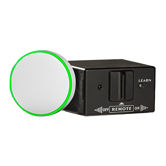
Receiver
Transmitter
ON
The transmitter (button) has a green and red LED light ring that ilimunates when you press and release the top button.
Tapping the transmitter one time, turns the appliance ON, emitting one green blink. Double tapping the transmitter turns
the appliance OFF, emitting two red blinks. If the LED light ring does not illuminate when tapping ON or OFF, check the
battery position and use a tester to ensure it has a minimum of 3 volts.
TRANSMITTER
Remove Battery
Cover
The transmitter operates on (1) 3-volt Lithium CR2450
button cell battery (included), capable of a 3 year battery
life.
Before using the transmitter, look for a small notch under
the battery cover and slide the cover toward the notch and
lift it off.
Underneath the battery is an insulation tab. Pull the tab out
from underneath the battery.
Tab
UP
Look for notch
Below the area where the battery is installed is a 3 position
CR2450
selector switch. The selector switch is not used with this
control system and should be left in the "1" position.
CR2450
Note: If the selector switch is set to either "2" or "3" the
Battery
LED light ring will illuminate orange when tapping the
button transmitter and the appliance will not turn ON.
Selector Switch
There is a low battery indicator built into the transmitter. A
1
red LED flash will blink once every 4 second indicating the
3
battery level is low.
2
Model: 7001
REV. 4-17-20 Page 1
Advertisement
Table of Contents

Subscribe to Our Youtube Channel
Related Manuals for Skytech 7001


Summary of Contents for Skytech 7001
- Page 1 MODEL: 7001 INSTALLATION AND OPERATING INSTRUCTIONS IF YOU CANNOT READ OR UNDERSTAND THESE INSTALLATION INSTRUCTIONS DO NOT ATTEMPT TO INSTALL OR OPERATE INTRODUCTION This remote control system was developed to provide a safe, reliable and user-friendly remote control system for gas heating appliances. This all battery system, operates independently of household current. The system operates on radio frequencies with a non-directional signals.
-
Page 2: Battery Removal
(positive + side up) under the metal clip first and into the cavity of the transmitter then press down until it snaps into Metal Clip place under the plastic tab. After battery is installed then replace the battery cover. Model: 7001 REV. 4-17-20 Page 2... -
Page 3: Installation Instructions
(included) be used to make connections between the terminal wiring block on the millivolt gas valve or electronic module and the wire terminals on the remote receiver. For the best results use wire with no splices and measuring no longer than 20-feet. Model: 7001 REV. 4-17-20 Page 3... - Page 4 The remote receiver can be placed on the fireplace hearth or under the fireplace, behind the control access panel. Position where the ambient temperature inside the receiver case does not exceed 130º F. NOTE: Black slide button (accessory pack) is used on Hearth Mount Applications. Model: 7001 REV. 4-17-20 Page 4...
-
Page 5: Wiring Instructions
ON. The spark electrode should begin sparking to ignite the pilot. After the pilot is lit, the main gas valve should open and the main gas flame should ignite. • Press the OFF button on the transmitter to OFF. The main gas flame and pilot flame should BOTH extinguish. Model: 7001 REV. 4-17-20 Page 5... -
Page 6: Troubleshooting
• Keep receiver from temperatures exceeding 130º F. Battery life shortened when ambient temperatures are above 130º F. • If receiver is installed in tightly enclosed metal surround, the operating distance will be shortened. Model: 7001 REV. 4-17-20 Page 6... - Page 7 When installation is complete, align the letters UP on the battery cover with UP letters on the transmitter then slide it into place a lock it. Inside of battery cover. DIMENSIONS (12mm) (52mm) ½” 2” Model: 7001 REV. 4-17-20 Page 7...
-
Page 8: Specifications
For Technical Service, call: CANADIAN INQUIRIES (877) 472-3923 (855) 498-8324 or (260) 459-1703 Skytech Products Group 9230 Conservation Way Fort Wayne, IN 46809 Sales: (888) 672-8929 Web site: www.skytechpg.com MANUFACTURED EXCLUSIVELY FOR SKYTECH II, INC Model: 7001 REV. 4-17-20 Page 8... -
Page 9: Limited Warranty
(the “Customer”) and expires upon any sale or transfer of the home where the System is installed by the Customer. 2. System Sold As Is. Subject to this Warranty and any applicable state law, each System is sold by Skytech to a Customer on an “as is”... - Page 10 REV. 2-24-17 Print information and detach at dotted line for return to: Skytech, ATTN WARRANTY DEPT., 9230 Conservation Way, Fort Wayne, IN 46809 Telephone: (855) 498-8324 Back of remote Date Code Sample...
Need help?
Do you have a question about the 7001 and is the answer not in the manual?
Questions and answers