Advertisement
Quick Links
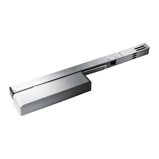
8900 EMF
(NO DETECTOR)
Each (HO) hold open unit contains a door closer and track assembly with hold open electromagnet.
The unit can be connected directly to a fire control panel.
1
. Read entire instruction sheet prior to installation and refer to NFPA 72E. Standards may be obtained from
THE NATIONAL FIRE PROTECTION ASSOCIATION, Batterymarch Park, Quincy, MA., 02269.
2
. Reference unit carton for mounting style and voltage.
3
. Prepare door and frame for fasteners using the appropriate template. Mark, drill and tap holes as indicated.
If surface wiring is used, omit 7/8" hole for wire access.
4
Install closer to door.
METAL FRAMES
QTY
(4)
QTY
(4)
8900T AND 8900DE
C
HINGES
L
(RIGHT HAND DOOR)
8900PT
C HINGES
L
(LEFT HAND DOOR)
www.dorma-usa.com
WOOD FRAMES
(LEFT HAND DOOR)
HINGES L C
(RIGHT HAND DOOR)
1-800-523-8483
5
Remove (1) wire access plug according to
the installation type. Any access hole can be used for
surface wiring installations.
HINGES C L
NOTE:
Three access wire
holes on optional
surface wired units only.
INS NO.
NOTE: NO TOP PLUG
ON PT MOUNTS
T & DE (RH)
SURFACE WIRING
INSPK NO. 08279520 Rev 08/13
1 of 5
08281000
PAGE
T & DE (LH)
08/13
Rev.
Advertisement

Related Manuals for Dorma EMR Series


Summary of Contents for Dorma EMR Series
- Page 1 (RIGHT HAND DOOR) (LEFT HAND DOOR) 8900PT C HINGES HINGES L C SURFACE WIRING (LEFT HAND DOOR) (RIGHT HAND DOOR) INSPK NO. 08279520 Rev 08/13 08/13 1 of 5 www.dorma-usa.com 1-800-523-8483 08281000 Rev. PAGE INS NO.
-
Page 2: Incoming Power Connection
8900T AND 8900DE Install track to frame. Install with wire access plugs toward latch edge of door using (2) 1/4-20 x 2" metal or (2) No. 14 x 2-3/4" wood screws. Route wires from frame through appropriate wire access hole in track, being careful not to pinch wires during installation. END CAP END CAP Install PT track to soffit with wire access plugs toward hinge. - Page 3 Attach main arm to door closer. With door in closed position, rotate spindle 45° with wrench. Place arm on 8900T spindle parallel to door and secure arm with pinion screw and washer. 6mm HEX KEY 6mm HEX KEY (RIGHT HAND DOOR) (LEFT HAND DOOR) With door in closed position, rotate spindle 45°...
- Page 4 Adjust spring tension, if required, using a 1/4" wrench. Adjust sweep, latch and backcheck valves. CAUTION: DO NOT REMOVE VALVES. NOTE: 8916 supplied with size 3 spring setting. 8956 supplied with size 6 setting. BACKCHECK RANGE CRITICAL SWEEP DELAYED RANGE DECREASE ACTION SPRING TENSION...
-
Page 5: Operation
15 Final installation and test. IMPORTANT: THE UNIT MUST BE TESTED AFTER THE 1. After installation is completed, recheck all INSTALLATION, BY THE END USER, TO ASSURE connections. Apply power to units. THAT THE DOOR CLOSER UNITS FUNCTION PROPERLY 2. Open door so slide block engages with hold WHEN THE ALARM SYSTEM IS ACTIVATED.
Need help?
Do you have a question about the EMR Series and is the answer not in the manual?
Questions and answers