Advertisement
Quick Links
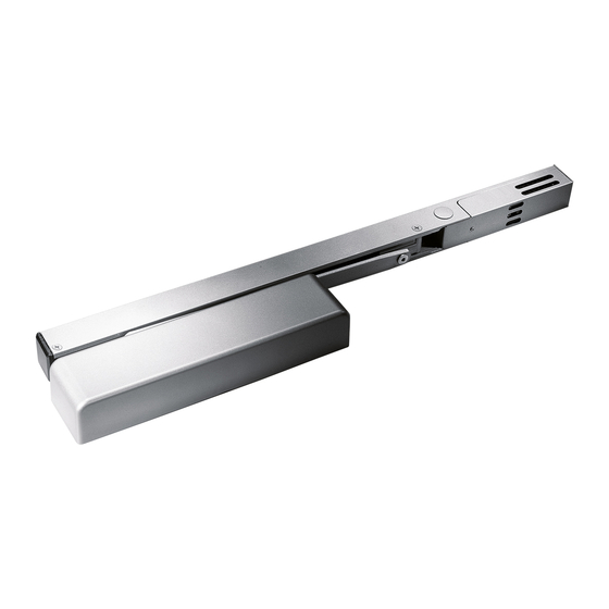
8600 EMF SERIES
Each (HO) hold open unit contains a door closer and track assembly with hold open electromagnet.
The unit can be connected directly to a fire control panel.
1 . Read entire instruction sheet prior to installation and refer to NFPA 72E. Standards may be obtained from
THE NATIONAL FIRE PROTECTION ASSOCIATION, Batterymarch Park, Quincy, MA., 02269.
2 . Reference unit carton for mounting style and voltage.
3 . Prepare door and frame for fasteners using the appropriate template. Mark, drill and tap holes as indicated.
If surface wiring is used, omit 7/8" hole for wire access.
1
Install closer to door.
8600T AND 8600DE
C L
(RIGHT HAND DOOR)
8600PT
C
L
(LEFT HAND DOOR)
www.dorma-usa.com
QTY
(4)
(LEFT HAND DOOR)
(RIGHT HAND DOOR)
1-800-523-8483
2
Remove (1) wire access plug according to
the installation type. Any access hole can be used for
surface wiring installations.
T & DE (RH)
NOTE:
Three access wire
holes on optional
C L
surface wired units only.
C
L
INSPK NO. 08280570 Rev.08/13
08281020
INS NO.
NOTE: NO TOP PLUG
ON PT MOUNTS
T & DE (LH)
SURFACE WIRING
1 of 5
Rev.
PAGE
08/13
Advertisement

Subscribe to Our Youtube Channel
Related Manuals for Dorma 8600 EMF Series


Summary of Contents for Dorma 8600 EMF Series
- Page 1 8600 EMF SERIES Each (HO) hold open unit contains a door closer and track assembly with hold open electromagnet. The unit can be connected directly to a fire control panel. 1 . Read entire instruction sheet prior to installation and refer to NFPA 72E. Standards may be obtained from THE NATIONAL FIRE PROTECTION ASSOCIATION, Batterymarch Park, Quincy, MA., 02269.
- Page 2 8600T and 8600DE Install track to frame. Install with wire access plugs toward latch edge of door using (2) 1/4-20 x 2" metal or (2) No. 14 x 2-3/4" wood screws. Route wires from frame through appropriate wire access hole in track, being careful not to pinch wires during installation. END CAP END CAP Install PT track to soffit with wire access plugs toward hinge.
- Page 3 Attach main arm to door closer. 8600T Place arm on top pinion as shown @45° angle. Secure with pinion screw and washer. 3/16 HEX KEY 3/16 HEX KEY (LEFT HAND DOOR) (RIGHT HAND DOOR) 8600DE Place arm on top pinion as shown @45° angle. Secure with pinion screw and washer. 3/16 HEX KEY 3/16 HEX KEY (LEFT HAND DOOR)
- Page 4 DO NOT REMOVE VALVES BACKCHECK POSITIONING ULC LABELED Adjuster UNITS ONLY Full Turns Door Width Max. Spring Size Door Weight 8616 8656 Interior Exterior 2'-6" (762) 2'-6" (762) 3'-0" (914) 3'-0" (914) 3'-6" (1067) 3'-6" (1067) 4'-0" (1219) FCSL Hold open position is preset at approximately 90°. Loosen set screws using 3/32 inch hex wrench.
-
Page 5: Operation
Final installation and test. IMPORTANT: THE UNIT MUST BE TESTED AFTER THE 1. After installation is completed, recheck all INSTALLATION, BY THE END USER, TO ASSURE connections. Apply power to units. THAT THE DOOR CLOSER UNITS FUNCTION PROPERLY 2. Open door so slide block engages with hold WHEN THE ALARM SYSTEM IS ACTIVATED.
Need help?
Do you have a question about the 8600 EMF Series and is the answer not in the manual?
Questions and answers