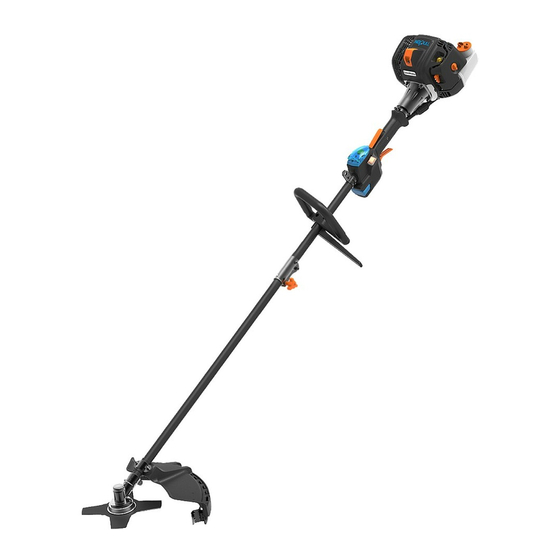
LawnMaster NPTBSP2609A Service Manual
26cc 2-cycle brush cutter
Hide thumbs
Also See for NPTBSP2609A:
- Operator's manual (88 pages) ,
- Instruction manual (47 pages) ,
- User manual

Subscribe to Our Youtube Channel
Related Manuals for LawnMaster NPTBSP2609A


Summary of Contents for LawnMaster NPTBSP2609A
- Page 1 SERVICE MANUAL 26cc 2-Cycle Brush Cutter NPTBSP2609A Read all safety rules and instructions carefully before servicing this tool. 601 Regent Park Court Greenville, SC 29607, 1-866-384-8432...
-
Page 2: Table Of Contents
CONTENTS Section Page CONTENTS SPECIFICATIONS GENERAL SAFETY RULES PARTS AND FEATURES 6-11 WIRING DIAGRAM AND MANAGEMENT GENERAL TROUBLESHOOTING 13-21 AIR & FUEL SYSTEM 22-29 THROTTLE AND STARTER SYSTEM 30-34 NOPULL™ STARTER SYSTEM 35-38 26CC 2-CYCLE ENGINE GEAR HEAD AND BRUSH CUTTER BLADE MANUFACTURER'S WARRANTY AND CONTACT... -
Page 3: Specifications
SPECIFICATIONS UNIT SPECIFICATIONS Engine Engine Size 2-Stroke / Full Crank Engine Displacement Claimed / Rated 26cc / 25.4cm Ignition Capacitor Discharge Ignition (CDI) Fuel System Carburetor All Position Diaphragm Type With Primer Bulb Air Filter Foam (Dry) Engine Shut Off Auto-Reset Throttle Control Variable Speed Trigger... - Page 4 SPECIFICATIONS Apply a thermostable screw-thread glue onto the Flywheel to crankshaft crankshaft thread. Pre-screw the flange hexagon nut 89-133 10-15 (M8) and then tighten. Slide the corrugated washers onto the clutch bolts (M6X21.5). Apply a thermostable screw-thread glue Clutch to flywheel onto the bolt thread head section.
- Page 5 SPECIFICATIONS Apply a thermostable screw-thread glue into the two Flywheel cover to holes on crankcase. Tighten the 2 screws (M5X15) 53-64 6-7.2 crankcase securing the flywheel cover to crankcase. 1.1-1.3 (for 10-12 Place the lower engine cover onto crankcase. Tighten 1*ST3.9X8) Lower engine cover the 3 screws (1*ST3.9X8, 2*M5X10) securing the...
-
Page 6: General Safety Rules
GENERAL SAFETY RULES SAFETY To protect the eyes from loose objects that could be thrown from the brush cutter, always wear eye protection with side shields marked to comply with ANSI Z87.1 when operating the brush cutter. Use only genuine manufacturer’s replacement parts for this product. Failure to do so may cause poor fit, poor function and possible injury. -
Page 7: Parts And Features
PARTS AND FEATURES NPTBSP2609A EXPLODED VIEW... - Page 8 PARTS AND FEATURES NPTBSP2609A PARTS LIST Application Description Quantity Number 641002101 Cleva 26cc 2-Cycle Engine 321001102 Throttle-body & Start Set 321001103 Throttle-body Set 321001104 Starter Set 2.2.1 321001105 Micro Switch 2.2.2 321001106 Starter Switch Assembly 2.2.3 321001107 Stop Switch Set 2.2.4...
- Page 9 PARTS AND FEATURES EXPLODED VIEW 26CC 2-CYCLE ENGINE...
- Page 10 PARTS AND FEATURES NPTBSP2609A PARTS LIST Application Description Quantity Number 321001130 Spark Plug Cover 321001131 321001132 Upper Engine Cover 321001133 Logo 321001134 Air Deflector 321002109 Cylinder Air Damper 321001136 Muffler Cover 321001137 Muffler 321001138 Insulation Sheet 321001139 Spark Plug 321002110...
- Page 11 PARTS AND FEATURES 321002127 Crankshaft Set 321002128 Piston Ring 321002129 Piston 321002130 Retainer Ring 321002131 Retainer Ring 321002132 Needle bearing 321002133 Piston Pin 321002134 Crankcase Assembly 641001126 Flywheel 321002143 Flange Nut M8 311014125 Flat Key 321002145 Clutch Assembly 321002146 Washer 321002147 Corrugated Washer 321002148...
-
Page 12: Wiring Diagram And Management
WIRING DIAGRAM AND MANAGEMENT - IGNITION AND STARTING Push-Start 2S Battery Pack Starter Switch (Self-reset) Panel Battery Connector VCC’ Battery Connector Bullet Terminal(BL) Electric PCB ASSEMBLY Motor Bullet Terminal(BL) Handle Engine Ignition lgnition Handle Stop Switch (Self-reset) 3.5 Bullet Terminal 3.5 Bullet Terminal Ignition Coil Spark Plug... -
Page 13: General Troubleshooting
GENERAL TROUBLESHOOTING PROBLEM POSSIBLE CAUSE SOLUTION The electric motor does The battery is not fully Charge the battery fully and insert it not start, and the battery charged or not inserted correctly. indicator LED flashes red. correctly. The motor does not start, Allow the battery to cool to room and the battery indicator The battery is overheated. - Page 14 GENERAL TROUBLESHOOTING No fuel. Add fuel to the fuel tank. The fuel tube is blocked. Remove the blockage. The carburetor nut loosens Tighten the carburetor nut or replace the and has air leakage. carburetor washer. Clean or replace the spark plug. Reset the spark plug gap.
- Page 15 GENERAL TROUBLESHOOTING Electrode of the spark plug Dry the spark plug. is wet. Spark plug has carbon Remove the carbon deposit. deposit. Spark plug insulation is Replace the spark plug. broken. Spark plug gap is too big/ Adjust to 0.026”±0.002” (0.65±0.05 mm). small.
- Page 16 GENERAL TROUBLESHOOTING Incorrect carburetor Re-adjust the carburetor. adjustment. The carburetor has an air Replace or re-tighten. leakage. No load speed is not stable/consistent. Fuel tube is broken. Replace. Crankcase washer has air Replace. leakage. Fuel seal has air leakage. Replace. Idle speed is too high.
- Page 17 GENERAL TROUBLESHOOTING Engine Compression (See Figs. 1-3) Low compression will cause erratic idling, low power, and hard starting when hot. To test the engine compression: ■ Remove the spark plug cover using the provided hex wrench (Fig. 1). ■ Remove the spark plug cap. Fully cover the spark plug using the provided socket wrench. Rotate the wrench counter-clockwise to remove the spark plug (Fig.
- Page 18 GENERAL TROUBLESHOOTING ■ Remove the spark plug cover. Remove the spark plug cap and the spark plug. Check and remove the carbon deposit in the spark plug. The spark plug gap should be 0.65±0.05mm. Inspect the electrodes for wear and deposits (Fig. 7). ■...
- Page 19 GENERAL TROUBLESHOOTING Clutch Replacement (See Figs. 12-18) ■ Remove the 4 screws to remove the transmission yoke (Fig. 12 & 13). Bolts Fig. 12 Fig. 13 ■ Remove the upper engine cover. ■ Unscrew the bolts on the clutch assembly using an impact driver or wrench (Fig. 14). ■...
- Page 20 GENERAL TROUBLESHOOTING ■ Turn the clutch upside down and slide the flat washers onto the bolts. Apply the thread-locking glue for 3-5 screw threads and then re-install the clutch (Fig. 17 & 18). Fig. 17 Fig. 18 Flywheel (Rotor) Replacement (See Figs. 19-22) ■...
- Page 21 GENERAL TROUBLESHOOTING Fig. 21 ■ Check the woodruff key is in good condition and installed into place. Examine it for signs of damage. Check if the rotor magnets meet the requirements. Check that the fins are in good condition. Replace with a new flywheel if necessary (Fig. 22). Fig.
-
Page 22: Air & Fuel System
AIR & FUEL SYSTEM Air Filter Replacement (See Figs. 23-26) ■ Rotate the air filter knob counter-clockwise and gently pull off the air filter cover (Fig. 23). ■ Remove the air filter from the air filter cover (Fig. 24). Air Filter Cover Air Filter Cover Air Filter Air Filter Knob... - Page 23 (clockwise or counter-clockwise) for reaching the max no load speed. Then turn the H screw slowly in the correct direction, and observe the RPM displayed on the tachometer until it reaches the max speed (Fig. 30). Max speed NPTBSP2609A About 10000-10800RPM...
- Page 24 AIR & FUEL SYSTEM CLOCK SET RESET Fig. 30 ■ Remove the carburetor adjustment tool and re-check the max no load speed. Engage and release the throttle trigger quickly to operate the cutter at full throttle, and observe the RPM displayed on the tachometer.
- Page 25 AIR & FUEL SYSTEM ■ Remove the carburetor adjustment tool and re-check the idle speed and the max no load speed again. Make sure they are correct (Fig. 33). CLOCK SET CLOCK SET RESET RESET Fig. 33 General Fuel Systems Operations (See Figs. 34-50) Carburetor Replacement ■...
- Page 26 AIR & FUEL SYSTEM ■ Remove the carburetor and the carburetor washer from the stud. Replace with a new one if necessary. Place the washer correctly with the hole upwards. Align the hole on washer with the hole on carburetor mount (Fig. 38 & 39). NOTE: Make sure the new carburetor and washer should be placed in the exact order in which they were removed.
- Page 27 AIR & FUEL SYSTEM ■ The choke lever is installed on the carburetor. Inspect the lever for signs of wear or damage and replace if needed. (Fig. 42). Fig. 42 Fuel Tank Replacement ■ Remove the upper engine cover. ■ Remove the 3 screws to remove the lower engine cover with the provided hex wrench and screwdriver (Fig.
- Page 28 AIR & FUEL SYSTEM ■ Remove the screw on the bottom of fuel tank (Fig. 47). Fig. 47 ■ Unplug the rubber plug in the front of fuel tank and remove the fuel tank (Fig. 48 & 49). Fig. 48 Fig.
- Page 29 AIR & FUEL SYSTEM Exhaust System Service (See Figs. 51-54) ■ Remove the upper and lower covers. ■ Remove the 3 screws to remove the muffler (Fig. 51 & 52). Fig. 51 Fig. 52 ■ Appropriate protective equipment is required when removing the muffler (Fig. 53). ■...
-
Page 30: Throttle And Starter System
THROTTLE AND STARTER SYSTEM Disassembly, Inspection & Repair of Throttle and Starter System (See Figs. 55-74) ■ Remove the 9 screws on the main handle (8 screws on the right cover and 1 screw on the left cover). Then remove the right cover of the main handle (Fig. 55 & 56). Fig. - Page 31 THROTTLE AND STARTER SYSTEM ■ Check the PCB assembly, microswitch, throttle safety and throttle lever. Replace if required (Fig. 59). Throttle Safety Microswitch Assembly Throttle Lever Fig. 59 ■ Use a proper tool (e.g. a screwdriver) to pry off the microswitch. ■...
- Page 32 THROTTLE AND STARTER SYSTEM ■ Restore the microswitch into place (Fig. 64). Fig. 64 ■ Connect the LED light cable to the electric starter cover plate. Always pull gently after assembly to ensure that terminals of the LED cable are connected in place (Fig. 65). Fig.
- Page 33 THROTTLE AND STARTER SYSTEM ■ Turn over the handle cover and re-install 1 screw (Fig. 68). Fig. 68 ■ To install the torsional spring and throttle safety, first pay attention to the correct direction of the torsional spring with the long end upwards as shown (Fig. 69). Make sure the throttle safety and the torsional spring are installed into place (Fig.
- Page 34 THROTTLE AND STARTER SYSTEM ■ Wrap the wiring harness of the engine with the opened corrugated pipe. One end of the wiring harness is exposed and another end of the power lines should be straightened out and thrust into the engine cover. ■...
-
Page 35: Nopull™ Starter System
NOPULL STARTER SYSTEM Special troubleshooting instructions for No-Pull™ Start Button (See Figs. 75-82) Starting Operation Lift the start button cover and press the start button to start the electric motor. Release the start button to stop the electric motor (Fig. 75). NOTE: When the start button remains pressed, the electric motor will run for about 5 seconds then it will stop automatically. - Page 36 NOPULL STARTER SYSTEM B. Red flashing of the battery indicator LED indicates that battery voltage is too low and needs to be charged. C. Green flashing of the battery indicator LED indicates that a short circuit occurs in the electric starter. Check the electric motor and the motor drive lines as below: Open the corrugated pipe buckle and disconnect the male and female terminals of the motor drive lines (blue) (Fig.
- Page 37 NOPULL STARTER SYSTEM F. If the battery indicator LED does not turn on, the possible causes are as below: 1). The microswitch is broken. Replace it. 2). The wiring harness of the microswitch has detached. Re-weld it. 3). There is failed contact in the battery connector to the PCB. Adjust the battery connector (Fig. 79).
- Page 38 NOPULL STARTER SYSTEM male and female terminals in the corrugated pipe buckle; 3). The stop switch has broken. Fig. 81 B. Test the stop switch wiring harness of the engine (Fig. 82). If conduction fails, the possible causes are: 1). An open circuit in the connection position between the wiring harness of the engine and the ignition coil;...
-
Page 39: 26Cc 2-Cycle Engine
26CC 2-CYCLE ENGINE Internal Engine Disassembly Inspection & Repair Engine Start Requirements and Inspection ■ Ignition System: Require a strong spark in the best ignition time. Inspection sequence (from exit to entrance): spark plug → spark plug cap → starter switch → high voltage line, ground line and on-off switch line →... -
Page 40: Gear Head And Brush Cutter Blade
GEAR HEAD AND BRUSH CUTTER BLADE Gear Head (See Fig. 83) After every 25 hours of use, check the level of grease inside the gear box and outside the axle. Add approximately 0.01 lbs. (5 g) of grease if necessary. The gear head of the straight shaft brush cutter has a left-hand rotation (Fig. -
Page 41: Manufacturer's Warranty And Contact
No-Pull LIMITED WARRANTY We take pride in producing a high quality, durable product. This LawnMaster® product carries a limited three (3) year warranty against defects in workmanship and materials from date of purchase under normal household use. This product carries a ninety (90) day warranty from the date of purchase when used for commercial or rental purposes.
Need help?
Do you have a question about the NPTBSP2609A and is the answer not in the manual?
Questions and answers