Sign In
Upload
Manuals
Brands
EDI Manuals
Measuring Instruments
CMU-212
EDI CMU-212 Manuals
Manuals and User Guides for EDI CMU-212. We have
1
EDI CMU-212 manual available for free PDF download: Operation Manual
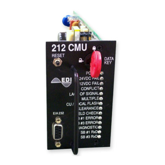
EDI CMU-212 Operation Manual (27 pages)
ITS Cabinet Monitor Unit
Brand:
EDI
| Category:
Measuring Instruments
| Size: 1.34 MB
Table of Contents
Table of Contents
3
Section 1 GENERAL
5
Overview
5
Channel Configuration
5
Auxiliary Monitor Unit
5
CMU-212 Programming
6
Detailed CMU Status
6
Eccom Software Interface
6
Auxiliary Display Unit
6
Serial Bus #1
7
Serial Bus #1 Message Types
7
Serial Bus #3
7
Serial Bus #3 Message Types
7
Failed State Action (LFSA, LFSA-R, NFSA)
7
Exit from FSA
8
Section 2 MONITOR FUNCTIONS
9
Cabinet Power Supply Monitor
9
Conflicting Channels Monitor
9
Serial Bus Monitor
9
Serial Bus #1 Error
9
Serial Bus #3 Error
9
Type 62 FSA Message
10
Lack of Signal Inputs Monitor
10
Multiple Input Monitor
10
Yellow Clearance Monitor
10
Yellow Plus Red Clearance Monitor
11
Local Flash Status
11
Local Flash Status Recovery
11
Circuit Breaker Trip Status
11
Flasher Unit Output Failed Alarm
11
CMU Power Failure
11
AC+ RAW Level Sense
12
Power Interrupt
12
Power Recovery
12
Power up
12
Minimum Flash Interval
12
Field Output Check
12
Field Check Mode
12
Field Check Status
13
Diagnostic Error
13
Ram Memory Diagnostic
13
Nonvolatile Memory Diagnostic
13
Datakey Memory Diagnostic
13
Internal MPU Monitor
14
Recurrent Pulse Detection
14
Recurrent Pulse Detection Disable
14
Flashing Yellow Arrow (FYA) Protected-Permissive Monitoring
15
FYA Configuration
15
Protected Turn Channel
15
Permissive Turn Channel
15
Opposing through Channel
15
Configuring the CMU-212 Fault Parameters for FYA
15
Conflict
16
Red Fail
16
Dual Indication
17
Minimum Yellow Clearance
17
Yellow Plus Red Clearance
17
Red and Yellow Input Enable
17
Flash Rate Detection
17
FYA Yellow Trap Conflict Detection
18
Section 3 INPUT SIGNALS
19
Field Signal Inputs
19
Load Switch Current
19
PDA Control Signal Inputs
19
Local Flash Status
19
Main Contactor (MC) Coil Status
19
Main Contactor (MC) Secondary Status
19
FTR Coil Drive Status
20
Circuit Breaker (CB) Trip Status
20
Front / Rear Door Switch
20
Monitor Interlock
20
External Test Reset Input
20
Serial Bus #1 Address Inputs
20
Serial Bus #1 Disable Input
21
PDA Temperature
21
Section 4 FRONT PANEL DESCRIPTION
22
Indicators
22
Power Indicator
22
24VDC FAIL Indicator
22
CONFLICT Indicator
22
LACK of SIGNAL Indicator
22
MULTIPLE Indicator
22
CU / LOCAL FLASH Indicator
22
CLEARANCE Indicator
22
FIELD CHECK Indicator
22
SB #1 ERROR Indicator
23
SB #3 ERROR Indicator
23
DIAGNOSTIC Indicator
23
SB #1 RX Indicator
23
SB #3 RX Indicator
23
Terminal Port
23
Reset Button
23
Datakey
23
Section 5 SPECIFICATIONS
24
Electrical
24
Timing
24
Mechanical
25
Environmental
25
Section 6 CONNECTOR ASSIGNMENTS
26
Main DIN Connector
26
EIA-232 Connector
26
Cmuip-212 Ethernet LAN Port
27
Ethernet LAN Cable
27
Advertisement
Advertisement
Related Products
EDI CMUip-212
EDI CMUip-2212 Series
EDI CMUip-2212-HV
EDI CMUip-2212-LV
EDI CMUip-2212-VHV
EDI CMU-24VDC-ITL Series
EDI 2010
EDI 2010ECL
EDI 2010ECLip
EDI 2018ECL
EDI Categories
Monitor
Measuring Instruments
Test Equipment
Industrial Electrical
Security Sensors
More EDI Manuals
Login
Sign In
OR
Sign in with Facebook
Sign in with Google
Upload manual
Upload from disk
Upload from URL