Table of Contents
Advertisement
Available languages
Available languages
Quick Links
Advertisement
Chapters
Table of Contents

Related Manuals for Riello RDBS1


Summary of Contents for Riello RDBS1
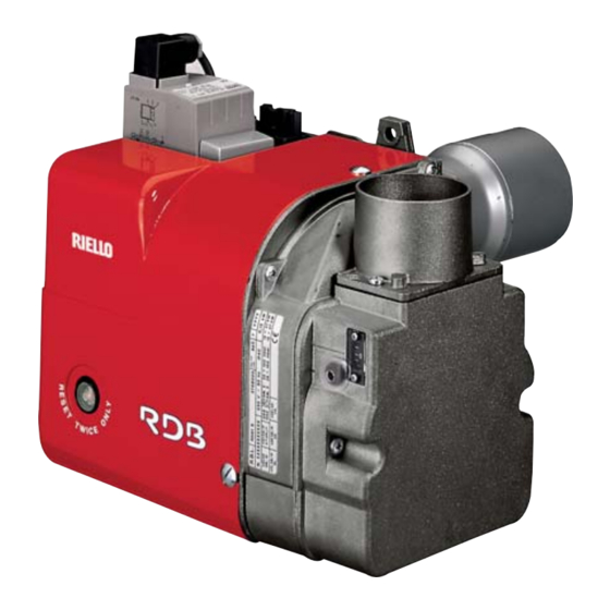
- Page 1 Installation, use and maintenance instructions Instructions pour installation, utilisation et entretien Forced draught gas burner Brûleur gaz à air soufflé One stage operation Fonctionnement à 1 allure CODE MODEL - MODÈLE TYPE 3768000 RDBS1 960T 2902768 (10) - 07/2015...
- Page 2 Original instructions Traduction des instructions d’origine...
- Page 3 The quality is guaranteed by a quality and management system certified in accordance with UNI EN ISO 9001. Legnago, 21.05.2015 Executive General Manager Research & Development Director RIELLO S.p.A. - Burner Department RIELLO S.p.A. - Burner Department Mr. U. Ferretti Mr. F. Comencini...
-
Page 4: Table Of Contents
INDEX BURNER DESCRIPTION....1 OPERATION ..... . . 9 1.1 Burner equipment . -
Page 5: Technical Data
TECHNICAL DATA 2.1 TECHNICAL DATA Type 960T Thermal power (1) 16 – 47 kW – 13,760 – 40,420 kcal/h Net heat value: 8 – 12 kWh/Nm = 7000 – 10,340 kcal/Nm Natural gas (Family 2) Pressure: min. 20 mbar – max. 65 mbar ±... -
Page 6: Firing Rate
2.3 FIRING RATE (as EN 676) D4206 kcal/h Thermal power TEST BOILER The firing rate has been defined according to EN 676 standard. COMMERCIAL BOILERS The burner-boiler matching is assured if the boiler is according to EN 303 and the combustion chamber dimensions are similar to those shown in the diagram EN 676.For applications where the boiler is not according to EN 303, or where the combustion chamber dimensions differ from those shown in EN 676, please consult the manufacturers. -
Page 7: Installation
INSTALLATION The installation of the burner must be carried out by qualified personnel, as indicated in this manual and in compliance with the standards and regulations of the laws in force. ATTENZIONE 3.1 BOILER FIXING Put on the flange (1) the screw and two nuts, (see fig. 2). ... -
Page 8: Gas Supply Line
The intake-tube / burner system must not allow a loss of over 2 m /h at 0.5 mbar: for instance, the above requirements will be met if you use flues for pressure exhaust of flue gases (the condensation kind). Make sure the air intake tube’s inlet is positioned so that it is not likely to be obstructed by foreign matter ... -
Page 9: Gas Train
3.4 GAS TRAIN (as EN 676) KEY TO LAY-OUT Type MBDLE 055 D01 1 - Gas supply pipe Natural gas and LPG 2 - Manual cock (Supplied by the installer) COMPONENTS 3 - Antivibration joint The multibloc is composed by : (Supplied by the installer) 1 - Filter 4 - Gas pressure gauge... - Page 10 FILTER MAINTENANCE If necessary the filter can be replaced; for this opera- tion you must call the service agent. PRESSURE STABILIZER ADJUSTMENT By rotating the pressure regulator adjustment screw clockwise, the gas head pressure & thus output increases. Anti-clockwise reduces the pressure & output.
-
Page 11: Electrical Wiring
3.5 ELECTRICAL WIRING NOTES: WARNING All the installation, maintenance and disassembly operations must be carried DO NOT EXCHANGE NEUTRAL WITH PHASE with electricity supply PERICOLO disconnected. 50Hz - 230V – Wires of min. 1 mm section. (Unless requested otherwise by local stand- ards and legislation). -
Page 12: Operation
3.6 PROBE-ELECTRODE POSITIONING Make sure that the ceramic Ionization is behind the diffuser disc and level with it. probe Diffuser Ignition electrode Probe Electrode D4202 WARNING 2.5 – 3.5 mm OPERATION 4.1 COMBUSTION ADJUSTMENT In conformity with Efficiency Directive 92/42/EEC the application of the burner on the boiler, adjustment and test- ing must be carried out observing the instruction manual of the boiler, including verification of the CO and CO concentration in the flue gases, their temperatures and the average temperature of the water in the boiler. -
Page 13: Combustion Check
SECONDARY AIR DAMPER (B) The purpose of this damper is to perform a fine-tuning of the inlet air. Tuning of this device is possible acting of the screw (3). Main air damper assembly (A) Secondary air damper (B) Fig. 6 D4202 D4202 4.4 COMBUSTION CHECK... -
Page 14: Air Pressure Test Point
4.5 AIR PRESSURE TEST POINT Fig. 8 ATTENTION Should the air pressure test point device (A) come loose by accident, you are advised to turn it to the correct position as illustrated in figure 8. Connect air pressure test point (A) to the pressure switch (C) inlet (-). -
Page 15: Maintenance
MAINTENANCE Notes on safety for the maintenance The periodic maintenance is essential for the good operation, safety, yield and duration of the burner. It allows you to reduce consumption and polluting emissions and to keep the product in a reliable state over time. The maintenance interventions and the calibration of the burner must only be carried out by qualified, authorised personnel, in accordance with the contents of this manual and in compliance with the standards and regulations of current laws. -
Page 16: Faults / Solutions
FAULTS / SOLUTIONS Below are some examples of causes & possible solutions that could result in the burner failing to operate or that result in it working incorrectly. A fault usually makes the lock-out lamp light which is situated inside the reset button of the control box (5, fig. - Page 17 FAULTS POSSIBLE CAUSES SOLUTION The pressure switch is faulty, change it. The air pressure switch does not change over to the operational posi- The developed air pressure is to low, tion. check the burner head setting. The burner locks out dur- The flame exists.
-
Page 18: Operating Fault Diagnostics
6.1 OPERATING FAULT DIAGNOSTICS The control box has a self-diagnostic system, which easily allows identifying the operating faults (RED LED signal). To use this function, wait at least ten seconds from the safety lock out, and then press the reset but- ton for a minimum of 3 seconds. - Page 19 La qualité est garantie grâce à un système de qualité et de gestion certifié conforme à UNI EN ISO 9001. Legnago, 21.05.2015 Directeur Général Directeur Recherche et Développement RIELLO S.p.A. - Direction Brûleurs RIELLO S.p.A. - Direction Brûleurs Ing. U. Ferretti Ing. F. Comencini...
-
Page 20: Description Du Bruleur
SOMMAIRE DESCRIPTION DU BRULEUR ..1 FONCTIONNEMENT ....9 1.1 Matériel fourni ..... . 1 4.1 Réglage de la combustion . -
Page 21: Donnees Techniques
DONNEES TECHNIQUES 2.1 DONNEES TECHNIQUES Type 960T Puissance thermique (1) 16 – 47 kW – 13,760 – 40,420 kcal/h Pci: 8 – 12 kWh/Nm = 7000 – 10,340 kcal/Nm Gaz naturel (Famille 2) Pression: min. 20 mbar – max. 65 mbar ±... -
Page 22: Plage De Travail
2.3 PLAGE DE TRAVAIL (selon EN 676) D4206 kcal/h Puissance thermique CHAUDIERE D’ESSAI La plage d’utilisation a été obtenue avec une chaudière d’essai conforme à la norme EN 676. CHAUDIERE COMMERCIALE L’accouplement brûleur / chaudière ne pose pas de problèmes si la chaudière est conforme à la norme EN 303 et si la chambre de combustion a des dimensions similaires à... -
Page 23: Installation
INSTALLATION L'installation du brûleur doit être effectuée par du personnel habilité, selon les indications reportées dans ce manuel et conformément aux normes et dispositions en vigueur. ATTENTION 3.1 FIXATION À LA CHAUDIÉRE Insérer sur la bride (1) la vis et deux écrous, (voir fig. 2). ... -
Page 24: Schéma Alimentation Du Gaz
Le tube de prise d'air / le système du brûleur ne doivent permettre une réduction de plus de 2 m /h à 0,5 mbar : par exemple, les exigences ci-dessus seront satisfaites si vous utilisez des conduits pour l'évacua- tion sous pression des fumées (à... -
Page 25: Rampe Gaz
3.4 RAMPE GAZ (selon EN 676) LEGENDE Type MBDLE 055 D01 1 - Conduit arrivée du gaz Emploi Gaz naturel et GPL 2 - Robinet de barrage (à la charge de l’installateur) COMPOSANTS 3 - Joint anti-vibrations Le multibloc comprend: (à... - Page 26 ENTRETIEN FILTRE En cas de nécessité, il peut être remplacé. Faites appel au Service Technique pour cette opération. REGLAGE DU STABILISATEUR DE PRESSION En tournant la vis dans le sens contraire aux aiguilles d’une montre on augmente la pression à la sortie, en tournant dans le sens contraire aux aiguilles d’une montre on diminue la pression.
-
Page 27: Installation Électrique
3.5 INSTALLATION ELECTRIQUE NOTES: ATTENTION Toutes les opérations d'installation, entretien et démontage doivent être NE PAS INVERSER LE NEUTRE AVEC LA PHASE effectuées avec le réseau électrique DANGER débranché. 50Hz - 230V – Section conducteurs: min. 1 mm (Sauf des indications différentes prévues par les normes et les lois locales). -
Page 28: Fonctionnement
3.6 POSITIONNEMENT SONDE - ELECTRODE Appuyer l’isolateur au disque de stabilisation Sonde Injecteur Electrode d’allumage Sonde Electrode D4202 ATTENTION 2,5 ÷ 3,5 mm FONCTIONNEMENT 4.1 RÉGLAGE DE LA COMBUSTION Conformément à la Directive rendement 92/42/CEE, le montage du brûleur sur la chaudière, le réglage et l’essai doivent être effectués en suivant le manuel de la chaudière, y compris en ce qui concerne le contrôle de la concentration de CO et CO dans les fumées, leur température et celle moyenne de l’eau de la chaudière. -
Page 29: Contrôle De La Combustion
VOLET D’AIR SECONDAIRE (B) Le volet d’air secondaire permet de compléter le réglage et se règle en agissant sur la vis (3). Réglage volet d’air primaire (A) Groupe volet d’air secondaire (B) Fig. 6 D4202 D4202 4.4 CONTRÔLE DE LA COMBUSTION Il est conseillé... -
Page 30: Prise De Pression Air
4.5 PRISE DE PRESSION AIR Fig. 8 ATTENTION Si la prise de pression de l’air (A) devait être desserrée accidentellement, il est recomman- dé de l’orienter correctement comme indiqué sur la figure 8. Relier la prise de pression de l’air (A) à l’en- ... -
Page 31: Entretien
ENTRETIEN Indications concernant la sécurité pour l'entretien L'entretien périodique est indispensable pour un bon fonctionnement, la sécurité, le rendement et la durée de vie du brû- leur. Il permet de réduire la consommation, les émissions polluantes et au produit de rester fiable dans le temps. Les interventions d'entretien et de réglage du brûleur doivent être effectuées par du personnel habilité, selon les indications reportées dans ce manuel et conformément aux normes et dispositions en vi- gueur. -
Page 32: Anomalies / Remedes
ANOMALIES / REMEDES La liste ci-dessous donne un certain nombre de causes d’anomalies et leurs remèdes. Problèmes qui se traduisent par un fonctionnement anormal du brûleur. Un défaut, dans la grande majorité des cas, se traduit par l'allumage du signal sur le bouton de réarmement manuel de la boîte de commande et de contrôle (5, fig. - Page 33 ANOMALIES CAUSES POSSIBLES REMEDES Le pressostat est défectueux, le rempla- cer. Le pressostat air n'a pas de courant. La pression d'air est trop basse (régler la Le brûleur se met en sé- tête). curité pendant la phase Flamme résiduelle. Vanne défectueuse: la remplacer. de préventilation.
-
Page 34: Diagnostic Mauvais Fonctionnement
6.1 DIAGNOSTIC MAUVAIS FONCTIONNEMENT La boîte de contrôle fournie de série a une fonction diagnostic qui permet de localiser facilement les causes possibles de mauvais fonctionnement (signalisation: LED ROUGE). Pour utiliser cette fonction, il faut attendre au moins dix secondes après la mise en sécurité de la boîte de contrôle et appuyer sur le bouton de déblocage pendant au moins trois secondes. - Page 36 RIELLO S.p.A. I-37045 Legnago (VR) Tel.: +39.0442.630111 http:// www.riello.it http:// www.riello.com Subject to modifications - Sous réserve de modifications...
Need help?
Do you have a question about the RDBS1 and is the answer not in the manual?
Questions and answers