
Related Manuals for Pentair BERKELEY LTH Series


Summary of Contents for Pentair BERKELEY LTH Series
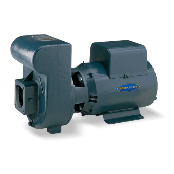
- Page 1 BERKELEY LTH SERIES SELF-PRIMING CENTRIFUGAL PUMP LTH-1 LTH-1-1/2 LTH-2 LTH-2-1/2 INSTALLATION AND OPERATION MANUAL pentair.com...
-
Page 2: Table Of Contents
TABLE OF CONTENTS SECTION ........................................PAGE Safety Infomation.....................................3 Installation....................................4-5 Electrical Installation..................................6 Operations....................................... 8 Maintenance....................................9-10 Repair Parts....................................11-12 Troubleshooting....................................13 Warrenty......................................15... -
Page 3: Safety Infomation
SAFETY INFORMATION Carefully read and follow all safety instructions in this manual GENERAL SAFETY or on pump.Keep safety labels in good condition. Replace missing or damaged safety labels. This is the safety alert symbol. When you see this symbol on Hazardous pressure! Install pressure relief your pump or in this manual, look for one of the following signal valve in discharge pipe. -
Page 4: Installation
INSTALLATION PRIOR TO PUMP INSTALLATION HORIZONTAL PIPING FROM WELL TO PUMP INSTALLATION • The well must not be more than 20 foot depth to water. Never install a suction pipe that is smaller than the suction • Long runs and many fittings increase friction and reduce port of the pump. - Page 5 INSTALLATION LAWN SPRINKLING APPLICATION This pump is designed for a pond, cistern or well points. Pump 1 0 0 discharge can be divided to supply two (2) or more sprinkler systems. A suggested multiple dis charge to service is shown in Figure 3.
-
Page 6: Electrical Installation
ELECTRICAL INSTALLATION WIRING Install, ground, wire and maintain this pump in accordance with electrical code requirements. Consult your local building inspector for information about codes. Read and follow all warnings below. Power Lead Terminals WARNING Hazardous voltage. Can shock, burn, or cause L1 and L2 death. - Page 7 ELECTRICAL INSTALLATION WIRING CHART RECOMMENDED WIRE AND FUSE SIZES HIGH HEAD Distance in Feet (Meters) From Motor to Supply 0' - 50' 51' - 100' 101' - 200' 201' - 300' Pump Max. Load Branch Fuse* Catalog # Phase, Volts Model Amps Rating* Amps...
-
Page 8: Operations
OPERATIONS PRIMING THE PUMP Priming refers to the pump expelling all air in the system and beginning to move water from its source out into the system. It does not refer only to pouring water into the pump (although pouring water in is usually the first step). Make sure suction and discharge valves and any hoses on discharge side of pump are open. -
Page 9: Maintenance
MAINTENANCE The pump and piping do not need to be disconnected to repair or replace the motor or seal. If motor is replaced, a new shaft seal must be installed. Keep an extra shaft seal on hand for future needs. Check motor label for lubrication instructions. - Page 10 MAINTENANCE NOTICE: Be sure not to nick or scratch carbon face of seal Remove rotating half of seal by placing two screw drivers under seal ring and carefully pry up (Figure 17). when passing it over threaded shaft end or shaft shoulder. Remove nuts from studs holding seal plate to motor.
-
Page 11: Repair Parts
REPAIR PARTS 2419A 0605 BE30 (11-21-19) - Page 12 REPAIR PARTS MODEL NUMBER ⁄ ⁄ LTH - 1 LTH - 1 LTH - 2 LTH - 2 Part Description 1 HP 2 HP 1-1.2 HP 2-1/2 HP Motor, 115/230V, 1 Phase A100ELL A100FLL — — Motor, 230V, 1 Phase —...
-
Page 13: Troubleshooting
TROUBLESHOOTING CHART Symptom Possible Cause(S) Corrective Action Disconnect switch is off Be sure switch is on Fuse is blown Replace fuse Starting switch is defective Replace starting switch Refer to instructions on wiring. Check and tighten all wiring. Motor will not run WARNING Capacitor voltage may be hazardous. - Page 14 This Page is Intentionally Left Blank BE30 (11-21-19)
-
Page 15: Warrenty
WARRANTY BERKELEY warrants to the original consumer purchaser (“Purchaser” or “You”) of the products listed below, that they will be free from defects in material and workmanship for the Warranty Period shown below. Product Warranty Period Water Systems: whichever occurs first: Water Systems Products —... - Page 16 *For a detailed list of where Pentair trademarks are registered, please visit www.pentair.com/en/registrations.html. Pentair trademarks and logos are owned by Pentair plc. or its affiliates. Third party registered and unregistered trademarks and logos are the property of their respective owners.
Need help?
Do you have a question about the BERKELEY LTH Series and is the answer not in the manual?
Questions and answers