Advertisement
Available languages
Available languages
Quick Links
GENERAL
M5004-24V electromotive actuators are used in many kinds of
control systems employed in HVAC applications, including
ON/OFF, floating, proportional managed by thermostat or
BMS handling analog signals.
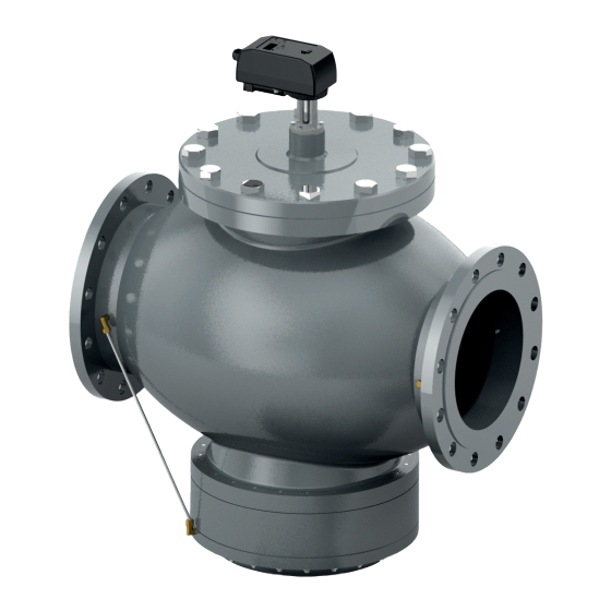
The V5004TF valve is designed to maintain a constant set
flow in spite of fluctuations in the pressure-drop.
Always protect the pressure regulator by using strainers
upstream of the valve and, in any case, make sure water
quality complies with VDI 2035 standards (Fe < 0.5 mg/kg
and Cu < 0.1 mg/kg).
Furthermore, the concentration of iron oxide in the water
passing through control valve (PICV) should not exceed 25
mg/kg (25 ppm).
To ensure the main pipework is cleaned appropriately,
flushing bypasses should be used without flushing through
the valve's pressure regulator, thereby preventing clogging.
Honeywell accepts no liability for improper use of this product.
® U.S. Registered Trademark
Copyright © 2019 Honeywell Inc. ▪ All Rights Reserved
KOMBI-QM VALVES
INSTALLATION INSTRUCTIONS
FEATURES
•
Commissioned actuator
•
Proportional flow control
•
Analog (voltage and current), floating, and ON/OFF
•
Position feedback
•
4-digit display
•
3 buttons to set parameters
•
Position control method to set the flow rate
INSTALLATION INSTRUCTIONS
1. Mount the valve with the arrow in the direction of
the flow
CAUTION
Mounting the valve in the wrong direction may
damage the system and the valve itself.
If flow reversal is possible, a non-return valve should be
mounted.
2. Observe Proper Orientation of the Valve!
The stem must be above the horizontal.
3. Avoid Mechanical Stress!
When mounting the valve, do not subject it to any undue
mechanical stress or strain! It is especially important that no
torque be applied to the actuator during mounting.
4. Operating Control
To ensure that the valve is working in its operating differential
pressure range, measure the differential pressure across the
valve.
Provided that the differential pressure is higher than the start-
up pressure, the valve keeps flow constant at the set value.
4a. Manual Override of the M5004
If it is necessary to manually open the valve, proceed as
follows:
1.
Remove the power supply from the motor.
2.
Open the rubber cover on the top of the actuator and
insert the 6 mm Allen key.
V5004TF
MU1B-0655GE51 R1019A
Advertisement

Subscribe to Our Youtube Channel
Related Manuals for Honeywell V5004TF Series


Summary of Contents for Honeywell V5004TF Series
- Page 1 4. Operating Control the valve's pressure regulator, thereby preventing clogging. To ensure that the valve is working in its operating differential Honeywell accepts no liability for improper use of this product. pressure range, measure the differential pressure across the valve.
- Page 2 V5004TF ACTUATOR – INSTALLATION INSTRUCTIONS Turn the key while continuing to push down the "release" button located on the bottom of the actuator. Fig. 1. Manual override M5004 4b. Valve-Actuator Assembly Fig. 2. Valve-actuator assembly MU1B-0655GE51 R1019A...
- Page 3 V5004TF ACTUATOR – INSTALLATION INSTRUCTIONS Table 1. Differential pressure at which valve exercises its regulating effect Pressure OS-No. Flow [I/h] Min. Max. Close-off V5004TF1050 2000 - 20000 V5004TF1065 3000 - 30000 V5004TF1080 3000 - 30000 V5004TF1100 5500 - 55000 V5004TF1125 9000 - 90000 V5004TF1150 15000 - 150000...
- Page 4 V5004TF ACTUATOR – INSTALLATION INSTRUCTIONS NOTE: To avoid damage due to condensation from the 6. Exercising and Cleaning valve stem, be sure that the actuator is not 6a. Weekly Exercising mounted upside down. Please note that care must be taken when installing the actuator: Even only To ensure continued smooth valve movement, the valve minor angular deviations can compromise proper should be operated (exercised) once a week over its entire...
- Page 5 V5004TF ACTUATOR – INSTALLATION INSTRUCTIONS Table 3. Display indications and meanings Indication Meaning Description (after 2 s) Input internal control in % (S-02 = int) Select type of input internal control using UP / DOWN buttons and then press MODE button to confirm. Input internal control in flow rate (S-02 = int) Voltage control signal...
- Page 6 V5004TF ACTUATOR – INSTALLATION INSTRUCTIONS Continuation of table (Display indications and meanings) Set flow rate in % Select using the UP / DOWN buttons and then press the MODE button to confirm. Set flow rate in "flow rate" Display option during operation: St permits the display of the flow rate value the controller requires.
- Page 7 V5004TF ACTUATOR – INSTALLATION INSTRUCTIONS Setting Parameter S-04: PRESETTING Table 4. Setting parameter S-04: Presetting V5004TF V5004TF V5004TF V5004TF V5004TF V5004TF V5004TF V5004TF V5004TF V5004TF Valve 1050 1065 1080 1100 1125 1150 1200LF 1200HF 1250LF 1250HF Max. pre- setting flow rate (m Min.
- Page 8 Selectable: 1 RPM or 1.5 RPM Manufactured for and on behalf of the Connected Building Division of Honeywell Products and Solutions SARL, Z.A. La Pièce, 16, 1180 Rolle, Switzerland by its Authorized Representative: Home and Building Technologies Honeywell GmbH Böblinger Strasse 17...
- Page 9 Ventil den Volumenstrom konstant auf dem Sollwert. 4a. Manuelle Übersteuerung M5004 Falls das Ventil von Hand geöffnet werden muß, gehen Sie folgendermaßen vor: Motor von der Spannungsversorgung nehmen. ® U.S. Registered Trademark Copyright © 2019 Honeywell Inc. ▪ All Rights Reserved MU1B-0655GE51 R1019A...
- Page 10 V5004TF STELLANTRIEB – INSTALLATIONSANWEISUNG Öffnen Sie den Gummideckel auf der Oberseite des Stallantriebs und stecken Sie den 6-mm-Inbussschlüssel ein. Drehen Sie den Schlüssel und halten Sie dabei den entsicherten Knopf unter dem Stellantrieb gedrückt. Abb. 1. Manuelle Übersteuerung M5004 4b. Ventil-Stellantrieb-Baugruppe Abb.
- Page 11 V5004TF STELLANTRIEB – INSTALLATIONSANWEISUNG Tabelle 1. Startdruck (Differenzdruck, bei dem die regulierende Wirkung des Ventils beginnt) Druck Artikel-Nr. Durchfluß [I/h] Min. Max. Schließdruck V5004TF1050 2000 - 20000 V5004TF1065 3000 - 30000 V5004TF1080 3000 - 30000 V5004TF1100 5500 - 55000 V5004TF1125 9000 - 90000 V5004TF1150 15000 - 150000...
- Page 12 V5004TF STELLANTRIEB – INSTALLATIONSANWEISUNG 6. Wartungslauf und Reinigung 6a. Wöchentlicher Wartungslauf Um die uneingeschränkte Beweglichkeit des Ventils zu ge- währleisten, sollte das Ventil mindestens einmal wöchentlich über seine volle Spanne betätigt werden (Wartungslauf). 6b. Reinigung Verwenden Sie zum Reinigen des Stellantriebs ein feuchtes Tuch.
- Page 13 V5004TF STELLANTRIEB – INSTALLATIONSANWEISUNG Tabelle 3. Display-Anzeigen und deren Bedeutung Anzeige Bedeutung Beschreibung (nach 2 s) Festsollwert Volumenstrom in % (S-02 = int) Auswählen mit der Nach-oben-/Nach-unten-Taste und Bestätigung mit der Modustaste. Festsollwert Volumenstrom in m /h (S-02 = int) Spannungs- 0…10 V-Steuerung mit Spannungssignal steuerungssignal...
- Page 14 V5004TF STELLANTRIEB – INSTALLATIONSANWEISUNG Fortsetzung Tabelle (Display-Anzeigen und deren Bedeutung) Volumenstrom in % Auswählen mit der Nach-oben-/Nach-unten-Taste und Bestätigung einstellen mit der Modustaste. Anzeigeoption während des Betriebs: Unter "flow rate" eingestellter Volumenstrom St ermöglicht das Anzeigen des vom Regler benötigten Volumen- stromwerts.
- Page 15 V5004TF STELLANTRIEB – INSTALLATIONSANWEISUNG Einstellung des Parameters S-04: VOREINSTELLUNG Tabelle 4. Einstellung des Parameters S-04: Voreinstellung V5004TF V5004TF V5004TF V5004TF V5004TF V5004TF V5004TF V5004TF V5004TF V5004TF Ventil 1050 1065 1080 1100 1125 1150 1200LF 1200HF 1250LF 1250HF Max. Voreinstell- ungs-Volumenstrom Min.
- Page 16 Laufgeschwindigkeit Auswählbar: 1 oder 1,5 U/Min. Hergestellt für und im Auftrag des Geschäftsbereichs Connected Building der Honeywell Products and Solutions SARL, Z.A. La Pièce, 16, 1180 Rolle, Schweiz in Vertretung durch: Home and Building Technologies Honeywell GmbH Böblinger Strasse 17 71101 Schönaich, Germany...
Need help?
Do you have a question about the V5004TF Series and is the answer not in the manual?
Questions and answers