Advertisement
Installation and Assembly:
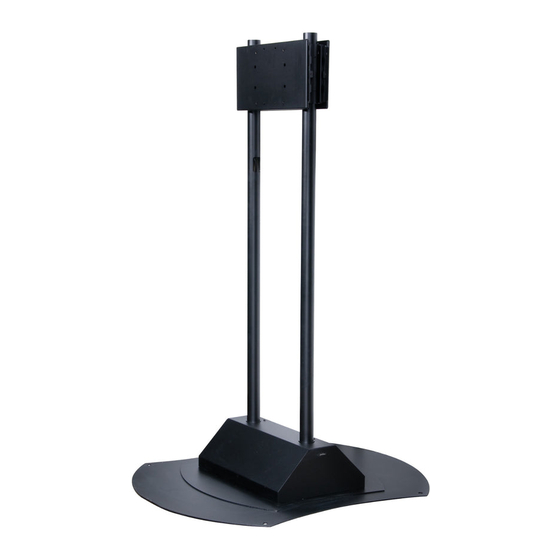
Flat Panel Stand for 50" - 71" Plasma Screens
Model: FPZ-670
Features:
• Fits single or back-to-back 50" - 71" flat panel screen
• Up to Vesa screens with additional PLP screen
• Supports non-Vesa screens with adapter plate (sold separately)
• Internal cable management to easily route cords from the screen to the base of the stand
• Base cover is designed to conceal content drivers and surge protectors
• Vertical adjustment on 6" columns for ideal screen viewing height
• Hook-on design allows screen to rest in place while screen is being secured
• Portrait or landscape orientation
Max Load Capacity 400 lb (181.4 kg)
200 lb (90.7 kg) Max Load Capacity per screen
Advertisement
Table of Contents

Related Manuals for peerless-AV FPZ-670


Summary of Contents for peerless-AV FPZ-670
- Page 1 Installation and Assembly: Flat Panel Stand for 50" - 71" Plasma Screens Model: FPZ-670 Features: • Fits single or back-to-back 50" - 71" flat panel screen • Up to Vesa screens with additional PLP screen • Supports non-Vesa screens with adapter plate (sold separately) •...
- Page 2 Note: Read entire instruction sheet before you start installation and assembly. WARNING • Do not begin to install your Peerless product until you have read and understood the instructions and warnings contained in this Installation Sheet. If you have any questions regarding any of the instructions or warnings, please call Peerless customer care at 1-800-729-0307.
- Page 3 Parts List Description Qty. Part # main tube 580-1159 base 104-1055 carriage 104-1063 adapter plate 104-1065 base cover 104-1068 cable access cover 130-1153 M5 x 8 mm socket pin screw 520-1062 M4 x 10 mm phillips screw 504-9012 M4 x 20 mm 504-9020 M6 x 12 mm pan head 520-1128...
- Page 4 For some situations, bumper strip (P) may be Slide two main tubes (A) onto base (B) and secure required to keep base (B) level. If so, cut bumper using four set screws (Q) as shown in figure 2 and strip (P) into five equal pieces and adhere one piece detail 1.
- Page 5 Slide carriage (C) onto main tubes (A). Slide carriage to desired height and secure using four set screws (Q) as shown in detail 1. Tighten screws using 4 mm allen wrench (T). Note: Orientation of "UP" arrow is critical. DETAIL 1 5 of 7 ISSUED: 05-08-08 SHEET #: 202-9280-1...
- Page 6 Attaching Adapter Plate to Screen with VESA 200 x 200 Mounting Pattern WARNING • If screws don't get three complete turns in the screen inserts or if screws bottom out and bracket is still not tightly secured, damage may occur to screen or product may fail. Choose hole pattern as shown in figure 6.1.
- Page 7 Portrait orientation Choose hole pattern as shown in figure 6.3. Attach adapter plate (D) to back of screen using four M10 x 15 mm screws (N) as shown. Tighten screws using 6 mm allen wrench (R). Note: Orientation of "UP" arrow is critical. fig 6.3 Hook adapter plate (D) onto carriage (C) and secure using two M6 x 20 mm serrated washer head socket pin screws (O) as shown in figure 5 and detail 3.
Need help?
Do you have a question about the FPZ-670 and is the answer not in the manual?
Questions and answers