Eaton CF2000 Installation Manual
Hide thumbs
Also See for CF2000:
- Installation and operation manual (100 pages) ,
- Application manual (94 pages)

Subscribe to Our Youtube Channel
Related Manuals for Eaton CF2000


Summary of Contents for Eaton CF2000
- Page 1 Effective June 2017 Technical Data PR202-50-502-22 Supersedes April 2016 CF2000 System Installation Manual...
-
Page 2: Table Of Contents
Commissioning CF2000 . . . . . . . . . . . . . . . . . . . -
Page 3: Introduction To The Manual
Cooper Fire Systems CF2000 System . Notice The operating system of the CF2000 may be revised as a result of enhancements to the system software or hardware . An updated issue of this manual is available on request . The current issue of the manual can also be downloaded from the Eaton website . -
Page 4: System Installation And Design
. Each loop of a CF2000 panel can accommodate up to 200 (99 Belgium) addresses . EATON www.eaton.com... -
Page 5: Project Planning
Systems should conform to the relevant local standards and codes of practice . For the UK this is BS5839 part 1 . CF2000 meets all the 1. Project Meeting relevant requirements of BS5839 part 1: 2002 . -
Page 6: Compatible Equipment
Description Dimensions (mm) CF2000GCPD CF2000GCPD 2 Loop CF2000 Panel 400H x 320W x 170D CF3000PRG CF3000PRG Loop Passive repeater for CF2000 270H x 332W x 92D 400002FIRE-0002X CAP320 Addressable Optical Sensor (CAP320) 101 Dia x 33D 400003FIRE-0003X CAH330 Addressable Heat Sensor (CAH330) - Page 7 Technical Data PR202-50-502-22 CF2000 System Effective June 2017 Compatible Equipment The range of compatible detectors for the CF2000 system consists of the following: Model CAP320 CAH330 CAPT340 Operating voltage 18 to 30V dc Standby current (max) 220μA Alarm current (max) Ambient Temperature (max) 50ºC...
- Page 8 -VE COM IN terminal and the -VE COM OUT terminal . The isolator operates in conjunction with the CF2000 Control Panel when a low parallel resistance fault of typically 200Ω is presented between the+VE and -VE of the loop wiring .
- Page 9 CF2000 multi stage cause and effect programming facilities . All sounders have multiple selectable volume settings, the volume setting is controlled by the CF2000 panel and so can be altered without needing to access the sounder . EATON www.eaton.com...
- Page 10 Base Sounder The CAS380 has been designed specifically to complement the latest generation of Eaton soft addressed detectors . It consists of a first fix bracket, and a main body which clips onto the bracket incorporating the sounder and a detector mounting base in a single composite assembly .
- Page 11 Technical Data PR202-50-502-22 CF2000 System Effective June 2017 Loop Powered Beacon A loop powered flashing beacon is available for applications where visual alarm indication is required such as areas of high ambient noise or buildings which are used by people who are hard of hearing .
-
Page 12: Interfaces
CF2000 System Effective June 2017 Interfaces CF2000 has been designed to be suitable for a wide range of applications, various interfaces have been developed to enable the simple integration of other fire systems or building control and safety systems . The following devices are available: 3 Channel I/O device (CIO351) CIO351 has 3 input channels and 3 output channels . - Page 13 Zone Monitor units CZMU352 CZMU352 is designed to enable a zone of compatible conven- tional detectors and callpoints to be connected into the CF2000 loop, it is compatible with up to 20 Menvier conventional detec- tors connected via CAB300 bases .
- Page 14 CF2000 control panel . A 4 way unit takes up a single address but each circuit can be independently controlled .
- Page 15 Technical Data PR202-50-502-22 CF2000 System Effective June 2017 Micro Interfaces A range of micro interfaces modules are also available: MIU872 is a compact single zone input, soft addressed, micro- interface, incorporating integral short circuit isolators . It is fully compatible with the current range of Cooper analogue fire detec- tion panels .
-
Page 16: Equipment Compatibility
. Relay circuits Additional relays can be added to the CF2000 system by using either CMIO353 or CIO351 relay units . Relays / Auto-dialers and auxiliary equipment... -
Page 17: System Overview
Simple user interface simplify the installation and commissioning processes . The main element of the user interface with CF2000 is a (60mm Once the system has been installed and the autolearn menu x 30mm visible area) display, which provides comprehensive user selected, the CF2000 control panel will automatically scan the information . -
Page 18: Technical Specification
Technical Data PR202-50-502-22 CF2000 System Effective June 2017 Technical Specification Power Supply (Approved EN54 pt 4) Mains Nominal Voltage 230V AC + 10%, -15% Nominal Current 40mA Maximum Current 500mA Input Fuse R1 Anti Surge 1 .6A Output Voltage including = 18 .5 to 29 .5V... - Page 19 This output is not to be used for Fire protecting equipment or Fire alarm routing Equipment Any power taken from the alarm system will affect the standby duration RS485 Port (Mimic Repeater) This is a serial output port for driving CF2000 Repeater panels, mimics etc . This output is short circuit protected Max Cable Length...
-
Page 20: Optional Functions As Per En54 Parts 2 & 4
Output to Fire Alarm Protecting Equipment (Option 7 .10 EN54 Part 2 Option A) CF2000 is approved to EN54 Parts 2 & 4 including all the options in this section which can be selected as required . Figure 3 on... -
Page 21: Installation
The screen should be earthed at the connection point provided • WHEN THIS SWITCH IS TURNED OFF at the CF2000 panel and not at any other point . Both the loop start and the loop end must be connected to the appropriate earthing points . -
Page 22: Fixing Details
The electronic components within the fire panel are Static Sensitive . Do not touch the electronics directly . Mounting the Backbox The CF2000 can be flush mount or surface mounted . For Surface Mount; drill four holes and fix the backbox to the wall . -
Page 23: System Wiring
Technical Data PR202-50-502-22 CF2000 System Effective June 2017 System Wiring Figure 3 shows a typical system wiring arrangement . Figure 3. Typical System Wiring diagram EATON www.eaton.com... -
Page 24: Commissioning Cf2000
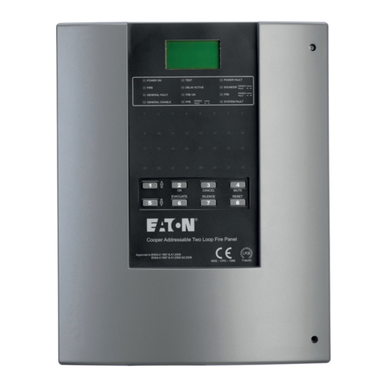
CF2000 System Effective June 2017 Commissioning CF2000 Up/downloading using PC software The PC Software enables the address, location text, device type and any comments to be downloaded to the CF2000 panels (Figure 5) . Figure 4. CF2000 front panel EATON www.eaton.com... -
Page 25: Device Input Programming
Technical Data PR202-50-502-22 CF2000 System Effective June 2017 Device input programming Figure 5. Device Inputs dialog Device Input Programming Fire Panel reports fire from device . Fault Panel reports fault from device . Reset Panel resets . Silence Silence all currently active sounders . -
Page 26: Device Outputs
Technical Data PR202-50-502-22 CF2000 System Effective June 2017 Device Outputs Figure 6. Device Outputs dialog Delay Configuration The output of a device when triggered can be delayed - based on a user defined value in minutes . This programming option is enabled when a value other than zero is entered inside the 'Delay' window . -
Page 27: Panel Outputs
Technical Data PR202-50-502-22 CF2000 System Effective June 2017 Panel Outputs Figure 7. Panel Outputs dialog Dependence detection Each panel output can be assigned a unique list of zones derived from the zones available on the loop . To activate this output, two unique zones from this list have to be in fire . -
Page 28: Panel Fault Finding
Technical Data PR202-50-502-22 CF2000 System Effective June 2017 Panel Fault Finding EATON www.eaton.com... -
Page 29: Protocol Format
Technical Data PR202-50-502-22 CF2000 System Effective June 2017 Protocol Format Figure 8. Full Protocol Format (not including repeaters) Normal Communications to Devices With the command bits set for the 'Normal' command and the MSB of the three mode bits set at 0, this shortened version of the Normal communications to each device allows the analogue reply or status from each device to be read . -
Page 30: Panel Controls And Indicators
Technical Data PR202-50-502-22 CF2000 System Effective June 2017 Panel Controls and Indicators Panel Overview Panel Display ① LCD Display ② System LEDs ③ Zonal LEDs ④ Buttons LED Display Name Function Action ① Power On Shows Panel is on (Mains Healthy) Check Indicator is Illuminated ②... -
Page 31: System Healthy
Effective June 2017 System Healthy CF2000 is operated via an 8 button keypad . The default healthy screen is shown below . From this screen all the panels functions can be operated . Press any key to prompt the passcode screen . -
Page 32: View Event
Technical Data PR202-50-502-22 CF2000 System Effective June 2017 View Event The View Events screen is shown below . The events screens are accessed from the healthy screen by first pressing any button . You will then be prompted to enter the passcode which will show the screen below by default . -
Page 33: Fire Event
Technical Data PR202-50-502-22 CF2000 System Effective June 2017 Fire Event The Fire screen is shown below . From this screen all the panels functions can be operated . Press any key to prompt the passcode screen Figure 12. Fire Event screen... -
Page 34: View Fires
Technical Data PR202-50-502-22 CF2000 System Effective June 2017 View Fires The View Fires screen is accessed as shown below . The events screens are accessed from the healthy screen by first pressing any button . You will then be prompted to enter the passcode which will show the screen below by default . -
Page 35: View Pre-Alarm
Technical Data PR202-50-502-22 CF2000 System Effective June 2017 View Pre-Alarm The View Pre-Alarm screen is accessed as shown below . The events screens are accessed from the healthy screen by first pressing any button . You will then be prompted to enter the passcode which will show the screen below by default . -
Page 36: View Fault
Technical Data PR202-50-502-22 CF2000 System Effective June 2017 View Fault The View Fault screen is accessed as shown below . The events screens are accessed from the healthy screen by first pressing any button . You will then be prompted to enter the passcode which will show the screen below by default . -
Page 37: View Disabled Address
Technical Data PR202-50-502-22 CF2000 System Effective June 2017 View Disabled Address The View Disabled Address screen is accessed as shown below . The events screens are accessed from the healthy screen by first pressing any button . You will then be prompted to enter the passcode which will show the screen below by default . - Page 38 Technical Data PR202-50-502-22 CF2000 System Effective June 2017 View Disabled Address (continued) Figure 17. View Disabled Address (continued) EATON www.eaton.com...
-
Page 39: View Disabled Zone
Technical Data PR202-50-502-22 CF2000 System Effective June 2017 View Disabled Zone The View Disabled Zone screen is accessed as shown below . The events screens are accessed from the healthy screen by first pressing any button . You will then be prompted to enter the passcode which will show the screen below by default . -
Page 40: View Disabled I/O
Technical Data PR202-50-502-22 CF2000 System Effective June 2017 View Disabled I/O The View Disabled I/O screen is accessed as shown below . The events screens are accessed from the healthy screen by first pressing any button . You will then be prompted to enter the passcode which will show the screen below by default . -
Page 41: View Log
Technical Data PR202-50-502-22 CF2000 System Effective June 2017 View Log The View Log screen is accessed as shown below . The events screens are accessed from the healthy screen by first pressing any button . You will then be prompted to enter the passcode which will show the screen below by default . -
Page 42: Operations (Soft Reset)
Technical Data PR202-50-502-22 CF2000 System Effective June 2017 Operations (Soft Reset) The Soft Reset screen is accessed as shown below . The Operations screens are accessed from the healthy screen by first pressing any button . You will then be prompted to enter the passcode which will show the events screen by default . -
Page 43: Operations (Evacuate)
Technical Data PR202-50-502-22 CF2000 System Effective June 2017 Operations (Evacuate) The Evacuate screen is accessed as shown below . The Operations screen is accessed from the healthy screen by first pressing any button . You will then be prompted to enter the passcode which will show the events screen by default . -
Page 44: Operations (Silence Alarms)
Technical Data PR202-50-502-22 CF2000 System Effective June 2017 Operations (Silence Alarms) The Silence Alarms screen is accessed as shown below . The Operations screens are accessed from the healthy screen by first pressing any button . You will then be prompted to enter the passcode which will show the events screen by default . -
Page 45: Operations (Lamp Test)
Technical Data PR202-50-502-22 CF2000 System Effective June 2017 Operations (Lamp Test) The Lamp Test screen is accessed as shown below . The Operations screens are accessed from the healthy screen by first pressing any button . You will then be prompted to enter the... -
Page 46: Operations (Weekly Test)
Technical Data PR202-50-502-22 CF2000 System Effective June 2017 Operations (Weekly Test) The Weekly Test screen is accessed as shown below . The Operations screens are accessed from the healthy screen by first pressing any button . You will then be prompted to enter the passcode which will show the events screen by default . -
Page 47: Access Level 2
Technical Data PR202-50-502-22 CF2000 System Effective June 2017 Access Level 2 Commissioning The Commissioning screen is accessed as shown below . The events screens are accessed from the healthy screen by first pressing any button . You will then be prompted to enter the pass- code which will show the screen below by default . -
Page 48: Panel Settings (Erase Log)
Technical Data PR202-50-502-22 CF2000 System Effective June 2017 Panel Settings (Erase Log) The Erase Log screen is accessed as shown below . The events screens are accessed from the healthy screen by first pressing any button . You will then be prompted to enter the passcode which will show the screen below by default . -
Page 49: Panel Settings (Change Password)
Technical Data PR202-50-502-22 CF2000 System Effective June 2017 Panel Settings (Change Password) The Change Password screen is accessed as shown below . The events screens are accessed from the healthy screen by first pressing any button . You will then be prompted to enter the pass- code which will show the screen below by default . -
Page 50: Panel Settings (Change Language)
Technical Data PR202-50-502-22 CF2000 System Effective June 2017 Panel Settings (Change Language) The Change Language screen is accessed as shown below . The events screens are accessed from the healthy screen by first pressing any button . You will then be prompted to enter the pass- code which will show the screen below by default . -
Page 51: Panel Settings (Date/Time)
Technical Data PR202-50-502-22 CF2000 System Effective June 2017 Panel Settings (Date/Time) The Date/Time screen is accessed as shown below . The events screens are accessed from the healthy screen by first pressing any button . You will then be prompted to enter the passcode which will show the screen below by default . -
Page 52: Panel Settings (System Details)
Technical Data PR202-50-502-22 CF2000 System Effective June 2017 Panel Settings (System Details) The System Details screen is accessed as shown below . The events screens are accessed from the healthy screen by first pressing any button . You will then be prompted to enter the pass- code which will show the screen below by default . -
Page 53: Testing (Test Device)
Technical Data PR202-50-502-22 CF2000 System Effective June 2017 Testing (Test Device) The Test Device screen is accessed as shown below . The events screens are accessed from the healthy screen by first pressing any button . You will then be prompted to enter the passcode which will show the screen below by default . -
Page 54: Testing (Test Zone)
Technical Data PR202-50-502-22 CF2000 System Effective June 2017 Testing (Test Zone) The Test Device screen is accessed as shown below . The events screens are accessed from the healthy screen by first pressing any button . You will then be prompted to enter the passcode which will show the screen below by default . -
Page 55: Testing (Test Sound Levels)
Technical Data PR202-50-502-22 CF2000 System Effective June 2017 Testing (Test Sound Levels) The Test Sound Levels screen is accessed as shown below . The events screens are accessed from the healthy screen by first pressing any button . You will then be prompted to enter the pass- code which will show the screen below by default . -
Page 56: Testing (One Man Walk Test)
Technical Data PR202-50-502-22 CF2000 System Effective June 2017 Testing (One Man Walk Test) The One Man Walk Test screen is accessed as shown below . The events screens are accessed from the healthy screen by first pressing any button . You will then be prompted to enter the pass- code which will show the screen below by default . -
Page 57: Testing (Global Flashing Led) Screen
Technical Data PR202-50-502-22 CF2000 System Effective June 2017 Testing (Global Flashing LED) screen The Global Flashing LED screen is accessed as shown below . The events screens are accessed from the healthy screen by first pressing any button . You will then be prompted to enter the pass- code which will show the screen below by default . -
Page 58: Testing (Analogue Levels)
Technical Data PR202-50-502-22 CF2000 System Effective June 2017 Testing (Analogue Levels) The Analogue Levels screen is accessed as shown below . The events screens are accessed from the healthy screen by first pressing any button . You will then be prompted to enter the pass- code which will show the screen below by default . -
Page 59: Device Config (Add Device)
Technical Data PR202-50-502-22 CF2000 System Effective June 2017 Device Config (Add Device) The Add Device screen is accessed as shown below . The events screens are accessed from the healthy screen by first pressing any button . You will then be prompted to enter the passcode which will show the screen below by default . -
Page 60: Device Config (Delete Device)
Technical Data PR202-50-502-22 CF2000 System Effective June 2017 Device Config (Delete Device) The Delete Device screen is accessed as shown below . The events screens are accessed from the healthy screen by first pressing any button . You will then be prompted to enter the pass- code which will show the screen below by default . -
Page 61: Device Config (Configure Zones)
Technical Data PR202-50-502-22 CF2000 System Effective June 2017 Device Config (Configure Zones) The Configure Zones screen is accessed as shown below . The events screens are accessed from the healthy screen by first pressing any button . You will then be prompted to enter the passcode which will show the screen below by default . -
Page 62: Appendix
Technical Data PR202-50-502-22 CF2000 System Effective June 2017 Appendix System Wiring A typical wiring arrangement is shown in Figure 41 Figure 41. Typical System Wiring EATON www.eaton.com... -
Page 63: Sounder Base Wiring
Technical Data PR202-50-502-22 CF2000 System Effective June 2017 Detector Base Wiring CAB300 Supply Voltage 18 - 30V DC Cable Size 0 .5 - 2 .5mm² Recommended cable types FIRETUF , FP200 or MICC Mounting Hole Centres 50 - 80mm Wiring Hints 1. -
Page 64: Call Point
Technical Data PR202-50-502-22 CF2000 System Effective June 2017 Call Point CBG370, CBG370/S, CBG370/WP Figure 43. Call Point EATON www.eaton.com... -
Page 65: Base Sounder Wiring
Technical Data PR202-50-502-22 CF2000 System Effective June 2017 Base Sounder CAS380 + CASBB384 Refer to Figure 44 for details of the base sounder wiring . Supply Voltage 17 ~ 32V DC Cable Size/type 0 .5 ~ 2 .5mm FIRETUF , FP200 or MICC Standby current <... -
Page 66: Loop Powered Beacon
Technical Data PR202-50-502-22 CF2000 System Effective June 2017 Loop powered beacon CAB382 Connection Details: Earth screen of cable to be continuous between beacons (Figure 45) . WARNING DO NOT USE HIGH VOLTAGE TESTERS IF ANY EQUIPMENT IS CONNECTED TO THE SYSTEM. -
Page 67: Internal Wall Sounder
Technical Data PR202-50-502-22 CF2000 System Effective June 2017 Internal Wall Sounder CAS381, CASB383 To install the device, fix to mounting surface using two suitable screws . The rear gasket fits underneath the base and the sounder gasket fits inside the base . -
Page 68: Ip66 Wall Sounder
Technical Data PR202-50-502-22 CF2000 System Effective June 2017 IP66 Wall Sounder Wiring CAS381WP , CASB383-WP To install the device 1. Drill required holes for the cable gland fixing 2. Drill out the required fixing holes 3. Fix to mounting surface using two suitable screws... -
Page 69: Way Input/Output Unit
Technical Data PR202-50-502-22 CF2000 System Effective June 2017 3 Way Input/Output unit CIO351, CIO351S, CIO351SST Install the device as follows . 1. Separate the two halves of the unit . 2. Drill out (or knock out) the required cable entries in the surface mounting back-box . -
Page 70: Way Input/Output Unit
Technical Data PR202-50-502-22 CF2000 System Effective June 2017 1 Channel Mains Rated I/O Wiring CMIO353 To install the device 1. Separate the two halves of the unit . 2. Drill out (or knock out) the required cable entries in the surface mounting backbox . -
Page 71: Zone Monitor Unit Wiring
Technical Data PR202-50-502-22 CF2000 System Effective June 2017 Zone Monitor Unit Wiring CZMU352 To install the device 1. Separate the two halves of the unit . 2. Drill out (or knock out) the required cable entries in the surface mounting backbox . -
Page 72: Intrinsically Safe Zone Monitor Unit
Technical Data PR202-50-502-22 CF2000 System Effective June 2017 Intrinsically Safe Zone Monitor Unit Wiring CZMU352-IS To install the device 1. Separate the two halves of the unit . 2. Drill out (or knock out) the required cable entries in the surface mounting backbox . -
Page 73: Shop Monitor Unit
Technical Data PR202-50-502-22 CF2000 System Effective June 2017 Shop Monitor Unit MSU840 To install the device 1. Separate the two halves of the unit . 2. Drill out (or knock out) the required cable entries in the surface mounting backbox . -
Page 74: Spur Isolator
1. Only connect cable screen to its adjacent earth terminal . 2. For maximum spur length / load see BS5839 Part1:2002 . 3. This unit can only be used with Eaton CAB300 detector bases and compatible sensors . EATON www.eaton.com... -
Page 75: Way Sounder Controller
Technical Data PR202-50-502-22 CF2000 System Effective June 2017 4 Way Sounder Controller CSC354CPR To install the device 1. Remove the cover of the unit . 2. Fit the back-plate in position and pass the wires into it taking care not to damage the circuit board . -
Page 76: Micro Zone Monitor Unit
Technical Data PR202-50-502-22 CF2000 System Effective June 2017 Micro Zone Monitor Wiring MIU872 To install the device 1. Fit the box in position using the mounting details below . 2. Connect the unit according to the diagram in Figure 55 . -
Page 77: Micro Input Module
Technical Data PR202-50-502-22 CF2000 System Effective June 2017 Micro Input Module Wiring MCIM To install the device 1. Fit the box in position using the mounting details below . 2. Connect the unit according to the diagram in Figure 56 . -
Page 78: Battery Disposal Instructions
Technical Data PR202-50-502-22 CF2000 System Effective June 2017 Battery Disposal Instructions Although batteries contain lead and small amounts of antimony and arsenic, they are safe if handled according to the accom- panying guide . The battery cells must not be dismantled as this involves several hazards, which are best handled under controlled conditions, using specialised equipment . -
Page 79: Ce Marking
Technical Data PR202-50-502-22 CF2000 System Effective June 2017 Eaton Electrical Systems Ltd Eaton Electrical Systems Ltd Wheatley Hall Road Wheatley Hall Road Doncaster Doncaster South Yorkshire South Yorkshire DN2 4NB DN2 4NB EN 54-2 1997 & A1:2006 EN 54-4 1997 & A1:2002 A2:2006... - Page 80 Eaton Industries Manufacturing GmbH Electrical Sector EMEA Route de la Longeraie 7 1110 Morges, Switzerland Eaton .eu .Eaton is a registered trademark . © 2017 Eaton All Rights Reserved June 2017 All other trademarks are property Publication No . PR202-50-502-22...
Need help?
Do you have a question about the CF2000 and is the answer not in the manual?
Questions and answers