Advertisement
Quick Links
Advertisement

Related Manuals for Lionel Railsounds Commander


Summary of Contents for Lionel Railsounds Commander
- Page 1 Railsounds Commander Instruction Manual Revised: October 2009...
-
Page 2: Cool Features
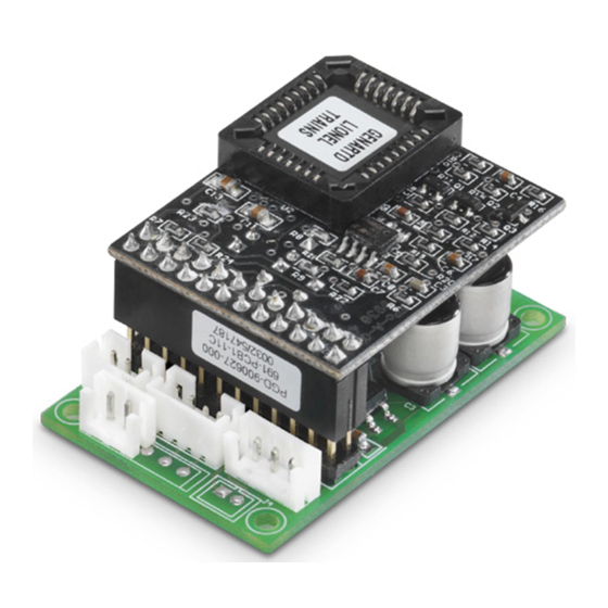
Only 1.95" L x 1.25" W x 0.95" H Overview The Electric Railroad Company RailSounds Commander is the smallest, most full featured, highest performance RailSounds 4.0 upgrade available for your locomotives. This innovative upgrade utilizes Lionel Railsounds 4.0 technology, combined with a single power controller that supports Command and conventional mode, including battery backup. -
Page 3: Parts Included
Parts Included • Railsounds Commander circuit board • Railsounds audio circuit board • Speaker & baffle • 3 Position to 4 position power & data cable assembly • 4 Position Battery & RS/SS switch cable assembly • Mounting hardware • Heat shrink tubing •... -
Page 4: Reference Diagrams
At the rear of this manual are the following diagrams which may be removed and placed nearby for easy reference while performing the steps in the instructions: Railsounds Commander Connector Pin Designations Wiring Diagram for Conventional Diesel & Electric Units Wiring Diagram for Conventional Steamers Wiring Diagram for Cruise Commander in Powered Diesel &... -
Page 5: Installation
Before beginning, please take time to read through all the instructions and plan out your installation. If other Electric Railroad Company products are being installed together with the Railsounds Commander, familiarize yourself with each one, as well as how they connect together. - Page 6 Snap the speaker into the baffle by applying pressure on the rim of the speaker only. 2. After test fitting the Railsounds Commander & Railsounds Audio Board together, carefully unplug the Railsounds Audio Board and set it aside before permanently mounting the Railsounds Commander circuit board.
- Page 7 Strip wire ends ¼ inch and then twist the exposed strands before making connections. The Railsounds Commander is a very flexible design that can be used in a wide variety of applications. As a result, all of the steps that follow will not be required to successfully complete a specific project.
- Page 8 Locate the 2 position VCO cable assembly which has two gray wires. Refer to Figure 4 and connect each wire to one of the motor brush wires or connections. It does not matter which wire goes where. Plug in the 2 position connector at the designated point on the Railsounds commander circuit board.
- Page 9 Without the switch, the full compliment of Railsounds is always enabled. To use these features, refer to Figure 5 and locate the 4 position Battery & RS/SS switch cable assembly. Plug in the 4 position connector at the designated point on the Railsounds commander circuit board.
- Page 10 Any connection from the switch to the chassis or to a chassis (AC) common connection will result in a destroyed Railsounds Commander. If no switch is being installed, either cut the blue wires at the connector or take...
- Page 11 For steamers, the Railsounds Commander will typically be mounted in the tender and the chuff trigger installed on a tender truck. To have synchronized chuffing, the chuff sensor switch will need to be installed in the locomotive, either on a wheel or the smoke unit lever on a piston type smoke unit.
- Page 12 Caution - Both of the orange wires must be connected directly to the reed switch sensor wires. Any connection from the reed switch sensor to the chassis or to a chassis (AC) common connection will result in a destroyed Railsounds Commander. 5. Power and Serial Data connections.
- Page 13 After the power and, if needed, the serial data connections are made, plug in the 3 position connector at the designated point on the Railsounds commander circuit board. Figure 10 shows an example conventional only connection and Figure 11 shows a typical Railsounds Commander to TMCC driver board connection.
- Page 14 Railsounds Commander circuit board. This will result in a destroyed Railsounds Commander. 6. All necessary connections to the Railsounds Commander should now be complete. Before continuing, double check all wiring and verify that there are no exposed wire...
-
Page 15: Final Assembly
1. Locate the Railsounds Audio board and, while referring to Figure 12, gently place it on the double row of pins on the Railsounds Commander circuit board. Take care to ensure that the Railsounds Audio board is properly aligned with all the pins before pressing into place. - Page 16 Repeat until the desired level is reached. When running in command mode, a CAB controller can be used to adjust the volume between this (maximum) level and no audible sound. The Railsounds Commander kit is now completely installed.
- Page 17 Interconnecting Railsounds Commander And Cruise Commander V 3.4 If interfacing a Railsounds Commander and a Cruise Commander, refer to Figure 1 and locate the Cruise Commander board version information. If the Cruise Commander is board version 3.4 or earlier then follow the instructions below. This Addendum does not apply to Cruise Commander boards that are version 4.0 and...
- Page 18 The yellow wire must be connected to + 5 volts, which is available at Pin 19 on the R2LC board. While referring to Figure 3 and Figure 4, carefully solder the yellow wire on the back side of the board. Notice that Pin 19 is the second pin under the “C“ in C21 and the third pin from the left edge of the board.
- Page 19 2. While referring to Figure 5, plug in the buffer cable assembly 3 position connector at the designated point on the Railsounds commander circuit board. Next, plug in the 4 position connector at J3 on the Cruise Commander circuit board.
- Page 20 The Railsounds Commander will normally remain silent when power is applied to the track and a solid TMCC signal is present. If a TMCC signal is not detected within 0.5 seconds then the Railsounds Commander may start up on its own. This is normal behavior.
- Page 21 The Horn/Whistle and Bell buttons on the transformer operate the respective sounds on the Railsounds Commander. The horn or whistle will sound as long as the button is pressed. The bell will stay activated until the Bell button is pressed again.
-
Page 22: Connector Pin Description
Brush 1 - Motor sense (VCO) input (Diesels) Brush 2 - Motor sense (VCO) input (Diesels) CAUTION – Railsounds Commander has both an AC Common and a separate DC Common. Connecting DC Common to AC Common will result in a... - Page 23 Brush 1 Brush 2...
- Page 25 Brush 1 Brush 2...
- Page 31 All manual contents are Copyright ©2009, The Electric Railroad Company. TMCC, CAB-1, R2LC, SignalSounds, RailSounds, Pullmor, and Magne-Traction are registered trademarks of Lionel, LLC. DCS is a registered trademark of MTH, Inc. Zap and Zap-A-Gap are registered trademarks of Pacer Technologies.
Need help?
Do you have a question about the Railsounds Commander and is the answer not in the manual?
Questions and answers