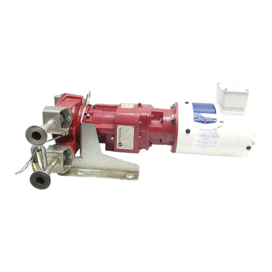
Hide thumbs Also See for Hose pump Series:
Table of Contents

Advertisement

Quick Links

Disc
The disc inserted in the front cover contains the user manual of the models Bredel 10,
Bredel 15 and Bredel 20. The user manual is available in the following languages:
The disc also contains quick-reference instructions for the replacement of the pump
hose. This replacement instruction is only for users that are familiar with the
replacement procedures in the user manual.
How to use the disc
1
Put the disc in the disc drive.
2
Close the disc drive.
The disc will start automatically.
3
Wait until the various language versions appear on screen.
4
Select the required language (click 1x with the left mouse button).
The PDF reader program will automatically start and the required user manual
appears on screen.
Shortcuts
In the left margin you will find the various chapters and paragraphs. These can be
accessed directly by clicking on the required chapter or paragraph.
In the text you will find hyperlinks to chapters or paragraphs. These hyperlinks are linked
with the required chapters or paragraphs. By clicking a shortcut the required chapter or
paragraph appears on screen.
System requirements
The program on the disc requires a PC with the following minimum system
requirements:
Disc drive
The following software must be installed on the PC:
PDF reader program
An Internet browser
1

Advertisement

Table of Contents
loading

Summary of Contents for Bredel Hose pump Series

  • Page 1 Disc The disc inserted in the front cover contains the user manual of the models Bredel 10, Bredel 15 and Bredel 20. The user manual is available in the following languages: The disc also contains quick-reference instructions for the replacement of the pump hose.
  • Page 3 Hose pump series Bredel 10, Bredel 15 and Bredel 20 Manual...
  • Page 4 Watson-Marlow Bredel B.V. The information provided can be changed without prior notification. Watson-Marlow Bredel B.V. or one of its representatives cannot be held liable for possible damage resulting from use of this manual. This is an extensive limitation of the liability which...
  • Page 5: Table Of Contents

    CONTENTS GENERAL How to use this manual ................8 Original instructions ................8 Other supplied documentation ..............8 Service and support ................8 Environment and disposal of waste ............9 SAFETY Symbols ....................10 Intended use ..................11 Use in potentially explosive atmospheres ..........11 Responsibility ..................
  • Page 6 INSTALLATION Unpacking .................... 22 Inspection ..................... 22 Installation conditions ................22 5.3.1 Ambient conditions ..............22 5.3.2 Set-up ..................22 5.3.3 Pipework ................... 23 5.3.4 Frequency controller ..............24 Lifting and moving the pump ..............25 Placing the pump .................. 25 COMMISSIONING Preparations ..................
  • Page 7 10.2.1 Pump head ................47 10.2.2 Gearbox ..................48 10.2.3 Electric motor ................48 10.2.4 Frequency controller ..............48 SPECIFICATIONS 11.1 Pump head ................... 49 11.1.1 Performance ................49 11.1.2 Materials ..................50 11.1.3 Surface treatment ..............51 11.1.4 Lubricant table pump ..............51 11.1.5 Weights ..................
  • Page 8: General

    Service and support For information with respect to specific adjustments, installation, maintenance or repair jobs which fall beyond the scope of this manual, contact your Bredel representative. Make sure you have the following data at hand: • Serial number hose pump •...
  • Page 9: Environment And Disposal Of Waste

    GENERAL Environment and disposal of waste CAUTION Always observe the local rules and regula- tions with respect to processing (non reus- able) parts of the hose pump. Enquire within your local government about the possibilities reuse environment-friendly processing of packaging materials, (contaminated) lubricant and oil.
  • Page 10: Safety

    SAFETY SAFETY Symbols In this manual the following symbols are used: WARNING Procedures which, if not carried out with the necessary care, may result in serious damage to the hose pump or in serious bodily harm. CAUTION Procedures which, if not carried out with the necessary care, may result in serious damage to the hose pump, the surrounding area or the environment.
  • Page 11: Intended Use

    European Directive 94/9/EC (ATEX). The pumps belong to: • Group II Appliances, category 2 GD bck T5 Use in Potentially explosive atmospheres requires special configuration of the pump unit. Contact your Bredel representative for use in explosive atmospheres.
  • Page 12: Responsibility

    Depending on the specific working conditions or accessories used, additional safety instructions can be required. Immediately contact your Bredel representative, if you noticed a potential danger while using your hose pump. WARNING The user of the hose pump is always fully responsible for observing the local valid safety regulations and directives.
  • Page 13: Warranty Conditions

    If parts are used that are not Watson-Marlow Bredel B.V. (hereafter called Bredel) parts, every warranty becomes void. Damaged parts which are covered by the applicable...
  • Page 14: Description

    The rotor identification letter identifies which type of rotor is mounted to the pump. The table below shows the rotor identification letter and the article number of the mounted rotor. Also refer to 11.5.3. Letter Bredel 10 Bredel 15-20 blank no rotor no rotor...
  • Page 15: Identification Of The Gearbox

    DESCRIPTION Letter Bredel 10 Bredel 15-20 210103H 215103H 220103L 220103H 210103X 215103X 220103X 4.1.4 Identification of the gearbox The identification plate on the gearbox contains the following data: Article number Serial number Type number Reduction ratio Number of revolutions per minute 4.1.5...
  • Page 16: Identification Of The Frequency Controller

    DESCRIPTION 4.1.6 Identification of the frequency controller The identification of the Bredel Variable Frequency Drive (VFD) can be found inside the VFD. Remove the cover by loosening the two screws. The identification sticker contains the following data: Article number Serial number 4.1.7...
  • Page 17: Construction Of The Pump

    DESCRIPTION Construction of the pump Cover Rotor Pump hose Pump housing Support Gearbox Electric motor Frequency controller Operation of the pump The heart of the pump head consists of a specially constructed pump hose (A) which lies contorted against the inside of the pump housing (B). Both ends of the hose are connected to the suction and discharge lines...
  • Page 18 DESCRIPTION (C). A bearing-mounted rotor (D) with two facing integral pressing shoes (E) is in the centre of the pump head. In phase 1 the lower shoe compresses the pump hose by the rotational movement of the rotor, forcing the fluid through the hose.
  • Page 19: Pump Hose

    The Bredel pump hoses have been carefully machined, therefore there are minimum tolerances in wall thickness. It is very important to guarantee the correct compression of the pump hose, because: •...
  • Page 20: Hose Compression Force Adjustment

    4.4.3 Lubrication and cooling The pumphead, in which the rotor and pump hose can be found, is filled with Bredel Genuine Hose Lubricant. This lubricant lubricates the movement between the hose and the pressing shoes and dissipates the generated heat via the pump housing and the cover.
  • Page 21: Electric Motor

    DESCRIPTION Electric motor If the electric motor has been standard supplied by the manufacturer, it is a standardized squirrel-cage motor. Refer to § 11.3 for specifications. If the pump is to be used in potentially explosive atmospheres, refer to chapter 10. Frequency controller Refer to the also supplied documentation of the supplier and §...
  • Page 22: Installation

    Inspection Check that your delivery is correct and check it for any transport damage. Refer to § 4.1.1. Report any damage immediately to your Bredel representative. Installation conditions 5.3.1 Ambient conditions...
  • Page 23: Pipework

    • The bore size of the suction and discharge lines must be larger than the bore size of the pump hose. For more information consult your Bredel representative. • Limit the presence of sharp bends in the discharge line.
  • Page 24: Frequency Controller

    INSTALLATION Maximum permissible loads [N] on the pump connections Force Bredel 10 Bredel 15 Bredel 20 5.3.4 Frequency controller WARNING A frequency controller that is fitted without the manual control can start automatically when power is applied. If the hose pump is fitted with a frequency controller, consider the following points: •...
  • Page 25: Lifting And Moving The Pump

    INSTALLATION Lifting and moving the pump For lifting and moving the hose pump, the pump support has a lifting eye (A). The complete hose pump, i.e. pump head, gearbox and electric motor, must be lifted using the lifting eye plus additional support using suitably rated straps or slings (A).
  • Page 26: Commissioning

    Check that the lubricant level is above the minimum level line in the inspection window. If necessary refill with Bredel Genuine Hose Lubricant via the breather plug. See also § 7.5. Commissioning Connect the pipework.
  • Page 27 Check the capacity of the hose pump. If the capacity differs from your specification, follow the instructions in chapter or consult your Bredel representative. Check the capacity range of the frequency controller. In case of any deviations consult the documentation of the supplier.
  • Page 28: Maintenance

    WARNING Only use original Bredel parts when main- taining the hose pump. Bredel cannot guarantee correct operation and any con- sequential damage that occurs from the use of non-original Bredel components.
  • Page 29 Check the gearbox for Before startup of the In case of leakage con- any leakage. pump and on a sched- sult your Bredel repre- uled interval during oper- sentative. ation. Check pump for deviat- On a scheduled interval See §...
  • Page 30: Additional Maintenance In Potentially Explosive Environments

    If a cleaning fluid is added to the water, check if the hose liner material is resistant to it. Also check if the pump hose can resist the cleaning temperature. Special cleaning balls are also available. Contact your Bredel representative for more details.
  • Page 31: Changing Lubricant

    MAINTENANCE Changing lubricant Place a tray (A) under the drain plug in the cover of the pump. Remove the drain plug (B). Catch the lubricant from the pump housing in the tray. Position the drain plug and tighten it firmly. The pump housing can be filled with lubricant via the breather (A) on the cover.
  • Page 32 MAINTENANCE Place a tray (A) under the drain plug in the bottom of the pump head. The tray must be large enough to contain the lubricant, possibly contaminated with product fluid, from the pump head. Remove the drain plug (B). Catch the lubricant from the pump housing in the tray.
  • Page 33: Cleaning The Pump Head

    Replace the cover and fasten the retaining bolts with the correct torque. Refer to § 11.1.6. Switch on the electrical supply to the pump. 7.6.3 Fitting the pump hose Clean the (new) pump hose on the outside and fully lubricate it with Bredel Genuine Hose Lubricant.
  • Page 34 MAINTENANCE Fit the pump hose (A) via one of the ports. Let the motor run to let the rotor pull the hose in the pump housing. Stop the motor when the hose sticks out equally from both sides of the pump housing.
  • Page 35: Exchanging Replacement Parts

    Now fit the other port. For this port proceed in the same way as described above for the inlet port. Fill the pump housing with Bredel Genuine Hose Lubricant. Refer to § 7.5. Connect the suction and discharge lines. Exchanging replacement parts 7.7.1...
  • Page 36 MAINTENANCE Put the hose pump on blocks. Make sure the space between the blocks is wide enough for the rotor to fall. Remove the nuts (B), the washers (C) and the pump drive (A). Put a plastic or wooden drive pin (A) on the rotor.
  • Page 37 MAINTENANCE Dismount the bearings (A), the spacer ring (B) and the retaining ring (C) with the correct tool. Clean the hub. Remove the seal ring (A). Clean and degrease the bore. Fit a new seal ring (A) using good engineering practises.
  • Page 38 MAINTENANCE Mount the circlip (A). Fit the rotor (A). The rotor is placed on the bearings with a loose fit. Press the rotor on the hub until it clicks on the retaining ring. Put the hose pump on two blocks. Fit the pump drive (A) with the nuts (B) and washers (C).
  • Page 39: Fitting Options

    MAINTENANCE Fitting options 7.8.1 Fitting a high-level float switch Dismount the standard breather (A) on the cover of the pump head. Mount the breather (A) with high-level float switch. Connect the high-level float switch to the auxiliary power circuit via the 2-metre long PVC cable (2 x 0.34 mm ).
  • Page 40: Revolution Counter

    MAINTENANCE Where the float switch is constructed to stop the equipment, operating has to be arranged so that the stop function locks out, preventing the equipment from being re-started without re-setting. Check if the float switch is mounted with the NC sign at the top.
  • Page 41: Storage

    STORAGE STORAGE Hose pump • Store the hose pump and pump parts in a dry area. Make sure that the hose pump and pump parts are not exposed to temperatures lower than -40 °C or higher than +70 °C. • Cover the openings of the inlet and outlet ports.
  • Page 42: Troubleshooting

    If the hose pump does not function (correctly), consult the following checklist to see if you can remedy the error yourself. If this is not the case, contact your Bredel representative. Problem...
  • Page 43 TROUBLESHOOTING Problem Possible cause Correction High pump temperature. Non standard hose lubri- Consult the Bredel repre- cant used. sentative for the correct lubricant. Low lubricant level. Add Bredel Genuine Hose Lubricant. For the required amount of lubricant refer to § 11.1.4.
  • Page 44 The filling degree of the Consult your Bredel repre- pump hose is too low, sentative for a recommen- because the speed is too dation. high in relation to the vis-...
  • Page 45 Reduce the line lengths on or high relative density or a both suction and dis- combination of these fac- charge where possible. tors. Consult your Bredel repre- sentative for a recommen- dation. Too narrow diameter of Increase the diameter of suction and/or discharge the suction/discharge lines.
  • Page 46 Insufficient or no hose Add extra lubricant. Refer pump. lubricant in the pump head. to § 7.5. Incorrect lubricant: no Consult the Bredel repre- Bredel Genuine Hose sentative for the correct Lubricant in the pump lubricant. head. Extremely high inlet pres- Reduce the inlet pressure.
  • Page 47: Hazardous Environments (Atex)

    HAZARDOUS ENVIRONMENTS (ATEX) HAZARDOUS ENVIRONMENTS (ATEX) 10.1 ATEX compliance Hose pumps that are configured for use in potentially explosive environments comply to CE directive 94/9/EC (ATEX directive). The hose pumps as mentioned on the front cover comply to: Group II Appliances, category 2 GD.
  • Page 48: Gearbox

    (EN 13463). 10.2.2 Gearbox The gearbox must be selected to meet your requirements concerning ATEX. Please contact your Bredel representative. 10.2.3 Electric motor The electric motor must be selected to meet your requirements concerning ATEX. Please contact your Bredel representative.
  • Page 49: Specifications

    SPECIFICATIONS SPECIFICATIONS 11.1 Pump head 11.1.1 Performance Description Bredel 10 Bredel 15 Bredel 20 Hose inner diameter [mm] Max. capacity, continuous [m 0.11 0.38 0.62 Max. capacity, intermittent [m 0.16 0.60 1.09 Capacity per revolution [l/rev] 0.022 0.083 0.152 Permissible ambient temperature [°C] -20 to +45 Permissible product temperature [°C]...
  • Page 50: Materials

    SPECIFICATIONS 11.1.2 Materials Description Material Pump housing Cast-iron Cover Cast-iron Pump rotor Cast-iron Pump support Galvanised steel (AISI 316 optional) Bracket AISI 316 Fasteners AISI 316 Seals, gaskets Seals, gaskets EPDM Coupling Steel...
  • Page 51: Surface Treatment

    Hose Lubricant Hose Lubricant Required quantity [litres] 0.25 Bredel Genuine Hose Lubricant is registered at NSF: NSF Registration N 123204; Category Code H1. See also: www.NSF.org/USDA. Should you require additional information with respect to the safety data sheet, consult your Bredel representative.
  • Page 52: Torque Figures

    SPECIFICATIONS 11.1.6 Torque figures Description Torques [Nm] Bredel 10 Bredel 15 - 20 Cover Hose clamp Bracket Support Inspection window 11.2 Gearbox Type Co-axial gearbox with helical gears Number of stages Two or three Lubrication Lubricated for life...
  • Page 53: Electric Motor

    230/400 V - 3 phases - 50 Hz 11.4 Variable Frequency Drive (VFD) (optional) The Bredel Variable Frequency Drive (VFD) has been preprogrammed and only needs to be connected to the mains. RFI filter Integrated RFI filter B (industrial applications).
  • Page 54: Parts List

    SPECIFICATIONS 11.5 Parts list 11.5.1 Overview Pos. Description Cover assembly. Refer to § 11.5.2. Pump head assembly. Refer to § 11.5.3. Pump support assembly. Refer to § 11.5.4. Barbed nipple assembly. Refer to § 11.5.5. Threaded nipple assembly. Refer to § 11.5.6. Flange assembly (1).
  • Page 55: Cover Assembly

    SPECIFICATIONS 11.5.2 Cover assembly Pos. Qty. Description Bredel 10 Bredel 15 Bredel 20 Cover 210102 215102 215102 Bolt, hex. head F504038 F504055 F504055 Washer F523010 F523012 F523012 Drain plug F911502 F911502 F911502 Gasket F342019 F342019 F342019 Inspection window 210155 215155...
  • Page 56: Pump Head Assembly

    SPECIFICATIONS 11.5.3 Pump head assembly Pos. Qty. Description Bredel 10 Bredel 15 Bredel 20 Hose NR 010020 015020 020020 Hose NBR 010040 015040 020040 Hose EPDM 010075 015075 020075 Hose CSM 010070 015070 020070 Pump housing 210101 215101 215101 Gasket...
  • Page 57: Support Assembly

    SPECIFICATIONS Pos. Qty. Description Bredel 10 Bredel 15 Bredel 20 Coupling, ∅ 20 x 63 mm 29063255 29063255 29063255 Coupling, ∅ 20 x 68 mm 29068255 29068255 29068255 Coupling, ∅ 25 x 63 mm 29064255 29064255 29064255 Coupling, ∅ 25 x 68 mm...
  • Page 58: Barbed Nipple Assembly (Ptfe/Pdvf)

    SPECIFICATIONS 11.5.5 Barbed nipple assembly (PTFE/PDVF) Pos. Qty. Description Bredel 10 Bredel 15 Bredel 20 Rubber bush 210119 215119 215119 Hose clamp C112507 C112508 C112508 Barbed nipple PTFE 210688010 215688015 215688020 Barbed nipple PVDF 210690010 215690015 215690020 Bracket 210197 215197 215197 Bolt, Hex.
  • Page 59: Barbed Or Threaded Nipple Assembly (Stainless Steel)

    SPECIFICATIONS 11.5.6 Barbed threaded nipple assembly (stainless steel) Pos. Qty. Description Bredel 10 Bredel 15 Bredel 20 Rubber bush 210119 215119 215119 Hose clamp C112507 C112508 C112508 Bracket 210197 215197 215197 Bolt, Hex. head F504036 F504054 F504054 Washer F532008 F532009...
  • Page 60: Flange Assembly (1)

    SPECIFICATIONS 11.5.7 Flange assembly (1) Pos. Qty. Description Bredel 10 Bredel 15 Bredel 20 Rubber bush 210119 215119 215119 Hose clamp C112507 C112508 C112508 Bracket 210197 215197 215197 Bolt, Hex. head F504036 F504054 F504054 Washer F532008 F532009 F532009 Threaded nipple (BSP) SS...
  • Page 61: Flange Assembly (2)

    SPECIFICATIONS 11.5.8 Flange assembly (2) Pos. Qty. Description Bredel 10 Bredel 15 Bredel 20 Rubber bush 210119 215119 215119 Hose clamp C112507 C112508 C112508 Flange bracket 210197A 215197A 215197A Bolt, Hex. head F504036 F504054 F504054 Washer F532008 F532009 F532009 Flange ASA...
  • Page 62: Revolution Counter Assembly

    Bredel 15 Bredel 20 Pump housing 210101A 215101A 215101A Revolution counter 29060367 29060367 29060367 Gasket ring F724009 F724009 F724009 11.5.10 Lubricants Pos. Qty. Description Bredel 10 Bredel 15 Bredel 20 0.5 l can Bredel Genuine 901143 901143 901143 Hose Lubricant...
  • Page 63: Ec Declaration Of Conformity Of The Machinery

    Directive 2006/42/EC: Peristaltic hose pump: Bredel 10-20 series, for the transportation of various kinds of fluids. In addition, the machinery complies with the harmonised standard(s), other standards or...
  • Page 64: Safety Form

    In compliance with the Health and Safety Regulations, the user is required to declare those substances that have been in contact with the item(s) you are returning to Watson-Marlow Bredel B.V. or any of its subsidiaries or distributors. Failure to do so will cause delays in servicing the item or in issuing a response. Therefore, please complete this form to make sure we have the information before receipt of the item(s) being returned.
  • Page 65 NOTES NOTES Notes...
  • Page 66 NOTES...
  • Page 67 NOTES...
  • Page 68 Watson-Marlow Bredel B.V. P.O. Box 47 NL-7490 AA Delden The Netherlands Telephone: +31 (0)74 3770000 Fax: +31 (0)74 3761175 E-mail: bredel@wmpg.com Internet: http://www.bredel.com © 2013 Watson-Marlow Bredel B.V.

This manual is also suitable for:

101520

Table of Contents