Table of Contents
Advertisement
Quick Links
Advertisement
Table of Contents

Related Manuals for uAvionix ping200X TSO


Summary of Contents for uAvionix ping200X TSO
- Page 1 ping200X User and Installation Guide UAV-1002373-001 DRAFT – TSO PENDING...
- Page 2 retained.
-
Page 3: Revision History
1 Revision History Revision Date Comments 10/22/2020 Initial release UAV-1002373-001 DRAFT – TSO PENDING... -
Page 4: Warnings / Disclaimers
2 Warnings / Disclaimers All device operational procedures must be learned on the ground. uAvionix is not liable for damages arising from the use or misuse of this product. This equipment is classified by the United States Department of Commerce's Bureau of Industry and Security (BIS) as Export Control Classification Number (ECCN) 7A994. -
Page 5: Limited Warranty
For the duration of the warranty period, uAvionix, at its sole discretion, will repair or replace any product which fails in normal use. Such... -
Page 6: Table Of Contents
Software ..............13 Environmental Qualification Form ..........14 Continued Airworthiness ............. 15 5.10 System Limitations ..............15 System Specifications ................ 16 System Functionality ..............16 ping200X TSO Specifications ............. 16 6.2.1 General Specifications............16 6.2.2 Mode S Transponder Specifications ........17 6.2.3 Altitude Encoder Specifications .......... - Page 7 Installation ..................19 Unpacking and Inspecting ............19 Authorized Part Numbers ............19 Installation Materials and Tools ........... 19 Additional Required Equipment ........... 20 Mounting ..................20 Wiring ..................21 Transponder Antenna ..............22 Static Pressure Port ..............23 Cooling Requirements ..............23 Control and Configuration Interface ...........
- Page 8 10.2 Control ..................30 10.3 Post-Installation Checks.............. 31 10.4 Software Part Number ..............33 10.5 Altitude Encoder Calibration ............34 11 Normal Operation ................35 12 Maintenance ..................35 13 Support ....................35 Appendix A Control Interface ..............36 Appendix B Position Interface ..............
-
Page 9: System Information
5 System Information 5.1 Certification This installation manual provides mechanical and electrical information necessary to install ping200X. It is not equivalent to an approved airframe- specific maintenance manual, installation design drawing, or installation data package. The content of this manual assumes use by competent and qualified personnel using standard maintenance procedures in accordance with Title 14 of the Code of Federal Regulation and other related accepted procedures. -
Page 10: Tso Authorization
5.2 TSO Authorization ping200X complies with the following TSOs when properly installed and interfaced with equipment as detailed in this guide. Function TSO / MPS Class / Type Air Traffic Control Radar Beacon Level 2els, TSO-C112e System/Mode Select (ATCRBS / Class 1 RTCA/DO-181E Mode S) Airborne Equipment... -
Page 11: Tso Deviations And Incomplete
TSO-C112e Paragraphs 3.e and 6.f to use RTCA/DO-178C in place of RTCA/DO-178B. C112e uAvionix was granted a deviation to not implement Utility Message (UM Field) support, consistent with anticipated RTCA/DO-181F and FAA/TSO-C112f Level 2 transponder requirements. -
Page 12: Fcc Id
C112e uAvionix was granted a deviation to not implement Air-Initiated Comm-B support, consistent with anticipated RTCA/DO-181F Level 2 and FAA/TSO-C112f transponder requirements. Air- initiated Comm-B messages are neither processed nor transmitted. This impacts the Mode S Level 2 transponder SARPs requirements as contained in ICAO Annex 10 Volume IV §§2.1.5.1.2 and 3.1.2.6.11.3. -
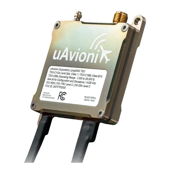
Page 13: Device Marking
5.7 Device Marking 5.7.1 ping200X Hardware 5.7.2 ping200X Software The software contained in ping200X is identified by electronic marking. Reference Section 10.4 for information on determining the software part number. UAV-1002373-001 DRAFT – TSO PENDING... -
Page 14: Environmental Qualification Form
5.8 Environmental Qualification Form DO-160G Conditions Description of Conducted Tests Section Temperature and Altitude Equipment tested to Categories B2,C4 Low temperature ground survival 4.5.1 -55°C Low Temperature Short-Time 4.5.1 -35°C Operating Low Temperature Operating 4.5.2 -35°C (see Note 1) High Temperature Operating 4.5.4 +70°C High Temperature Short-Time... -
Page 15: Continued Airworthiness
5.9 Continued Airworthiness Maintenance of the ping200X is "on condition" only. Periodic regulatory function checks of the transponder and altitude encoder must be performed. The aircraft must be returned to service in a means acceptable to the appropriate aviation authority. If the altitude encoder reports correspondence errors in excess of ±125 feet, when compared to the primary flight altimeter, then calibration as described in Section 10.5 must be performed. -
Page 16: System Specifications
This transponder replies to both legacy Mode A/C interrogations and to Mode S interrogations from both ground radar and airborne collision avoidance systems. In all cases, the interrogations are received by the transponder on 1030MHz and replies are transmitted on 1090MHz. 6.2 ping200X TSO Specifications 6.2.1 General Specifications Characteristics Specifications Width 46.99 mm... -
Page 17: Mode S Transponder Specifications
6.2.2 Mode S Transponder Specifications Characteristics Specifications Transmit frequency 1090 MHz Transmit power 54 dBm (250 W) Receive frequency 1030 MHz ATCRBS sensitivity -74 dBm Mode S sensitivity -74 dBm 50 Ω RF Impedance RF Connector 6.2.3 Altitude Encoder Specifications Characteristics Specifications Operating Range... -
Page 18: Control Interface Specifications
6.2.4 Control Interface Specifications Characteristics Specifications Physical RS-232 Rate and properties 57,600 bps 8N1 Protocols UCP, UCP-HD and Apollo For more control interface details, see Appendix A . 6.2.5 Position Interface Specifications Characteristics Specifications Physical RS-232 Rate and properties 115,200 bps 8N1 Protocols MAVLink For more position interface details, see Appendix B . -
Page 19: Installation
Software UAV-1002393-( ) 7.3 Installation Materials and Tools ping200X requires configuration, either using the available uAvionix Windows-based application, or dynamically using the described configuration protocol. Typical installations will be configured using: • “ping200X Control & Config” Windows application, UAV-1004567-( ) •... -
Page 20: Additional Required Equipment
7.4 Additional Required Equipment ping200X is a “remote” transponder. To fully function it requires connection to a controlling device, often referred to as a control head. It is possible to statically configure ping200X, but certain capabilities, such as changing the squawk code and responding to annunciations, will not be available when no controlling device is connected. -
Page 21: Wiring
7.6 Wiring ping200X requires connections to power, ground, an RS-232 control interface and an RS-232 position interface. 4-wire Control Interface Color Type Function Power Aircraft Power Input Power Black Aircraft Ground Input Data Grey Control RS-232 Transmit Output Data Orange Control RS-232 Receive Input 3-wire Position Interface... -
Page 22: Transponder Antenna
Take into consideration the antenna manufacturer’s installation instructions. General guidance is provided below. • The antenna should be mounted in a vertical orientation when the aircraft is in level flight. For uAvionix UAV-1000653-008, see below for proper orientation. UAV-1002373-001 DRAFT – TSO PENDING... -
Page 23: Static Pressure Port
• Keep the cable lengths as short as possible and avoid sharp bends in the cable to minimize the Voltage Standing Wave Ratio (VSWR) (i.e. Return Loss). • Ensure that cable and connector losses do not reduce power output below allowed levels for your aircraft operation. •... -
Page 24: Control And Configuration Interface
(SIL/SDA value). Amongst other considerations, position source and system latency must be considered. The following position source has been qualified for use: • uAvionix truFYX, P/N UAV-1002809-001 (SIL=3 / SDA=2) For details on the ping200X position interface, refer to Appendix B . 10 Configuration and Calibration The transponder system should be configured during initial system installation. - Page 25 USB Adapter Control POWER (9-30.3 V) ping200X Set ‘Conn Type’ to ‘Serial’, ‘Port’ to the USB or serial port connected to the ping200X, ‘App Baud’ to ‘57600’ and ‘Protocol’ to ‘UCP’. Verify the COM Settings Click ‘Start’. UAV-1002373-001 DRAFT – TSO PENDING...
-
Page 26: Configuration
10.1 Configuration The configuration items list below should be used to document the system installation for future reference. These items can be found on the ‘Configuration’ tab and are permanently stored in the ping200X. Configuration Item Default Configured ICAO Address 0x000000 Aircraft Maximum Speed (kts) <... -
Page 27: Aircraft Maximum Speed
Tip: By using the N-Number Look Up function on https://www.faa.gov, locate and use the “Mode S Code (base 16 / hex)” value. Applies to U.S. registered aircraft only. 10.1.2 Aircraft Maximum Speed Mode S transponders can transmit their maximum airspeed characteristics to aircraft equipped with TCAS. -
Page 28: Gps Antenna Lateral / Longitudinal Offset
Note: This is typically your aircraft N-number, unless otherwise advised by the FAA or ATC. 10.1.6 GPS Antenna Lateral / Longitudinal Offset The GPS antenna offset is used in conjunction with the length and width to manage taxiway conflicts. A typical GPS does not report the geographic position of the center of the aircraft, or even the tip of the nose of the aircraft;... -
Page 29: Baro Altitude Source
10.1.9 Baro Altitude Source By default, ping200X utilizes pressure altitude measurements from an internal TSO-C88b altitude encoder for Mode C, S and ADS-B messages. If desired, an existing or external altitude encoder can be used in lieu of the internal altitude encoder. To do so, change the ping200X’s “Baro Altitude Source”... -
Page 30: Default Squawk
10.1.13 Default Squawk The default squawk is 1200. To assist ATC tracking of aircraft, an aircraft squawk is transmitted. The configured value is the squawk code that will be transmitted in lieu of available control data. 10.1.14 Baro Altitude Resolution The barometric pressure altitude source resolution default is 25 (ft). -
Page 31: Post-Installation Checks
10.3 Post-Installation Checks Post-installation checks must be performed by the installer, after configuration, as appropriate for the aircraft and type of installation. To ensure compliance with regulations in the United States, verify functionality identified in 14 CFR Part 43 Appendix F (ATC Transponder Tests and Inspections) and 14 CFR Part 43 Appendix E (Altimeter System Test and Inspection). - Page 32 STEP CHECK Select ‘ALT’ from the ‘Mode’ selection box in ‘Control’ Verify ‘TX System’ fault annunciation LED turns green in ‘Fault Status’ If you are in range of Radar or connected to an interrogating test set, ‘Transponder Status’ will indicate interrogations If not already in airborne state, access the ‘Service’...
-
Page 33: Software Part Number
Launch the ‘ping200X Control & Config’ Windows application. Confirm the displayed ‘P/N’ and ‘Version’ on the ‘Firmware Version’ section of the ‘Service’ tab is current per Service Bulletins listed at: https://uavionix.com/support/ping200X/ If not current, apply Service Bulletins as appropriate to update the software. UAV-1002373-001... -
Page 34: Altitude Encoder Calibration
10.5 Altitude Encoder Calibration STEP CHECK Launch the ‘ping200X Control & Config’ Windows application Set Port to the USB or serial port connected to the ping200X Set the ‘App Baud’ to value noted in Section 10.1 Set ‘Protocol’ to value noted in Section 10.1 Apply power from a minimum of a 11V, 1A power source UAV-1002373-001 DRAFT –... -
Page 35: Normal Operation
ALT mode, during all phases of flight including surface movement operations. 12 Maintenance The ping200X is not a user serviceable product. All service must be performed either by uAvionix or an authorized uAvionix repair center. 13 Support For additional questions or support please visit: https://www.uavionix.com/support/ UAV-1002373-001 DRAFT –... -
Page 36: Appendix A Control Interface
Transponder Configuration message. UCP or UCP-HD input is required to be enabled to allow device configuration. A.1 UCP uAvionix Control Protocol (UCP) is documented in uAvionix UCP Transponder Interface Control Document UAV-1002375-001. This document is made available to authorized parties, and may be obtained by contacting uAvionix. - Page 37 Mode To set the transponder operating mode, appropriate enable bits must be set in the Control message. The mapping of traditional transponder modes to required Control message enablement bits follows. Operating Mode Mode A Mode C Mode S 1090ES STBY ON (suppress altitude) Flight Identification...
- Page 38 Unable to communicate with GNSS subsystem (RTCA/DO- Unavailable 260B §2.2.11.6) A.2 UCP-HD uAvionix Control Protocol – Half Duplex (UCP-HD) is documented in uAvionix UCP Transponder Interface Control Document UAV-1002375- 001. This document is made available to authorized parties, and may be obtained by contacting uAvionix.
- Page 39 A.3 Apollo Apollo can be used to control and monitor status of the ping200X. To use, ensure Apollo is enabled as an input protocol. Once an Apollo message is received, Apollo message output is enabled until device reset. A.3.1 Supported Input Messages The following input messages are supported: Mode (#MD) The Mode message configures the operating mode, Mode A (squawk)
-
Page 40: Appendix B Position Interface
The position interface communicates using the MAVLink protocol format, and accepts custom uAvionix “Navigation Data Messages”. This message is documented in the uAvionix OEM Protocol Specification UAV-1001912- 001. This document is made available to authorized parties, and may be obtained by contacting uAvionix. -
Page 41: Appendix C Example Installations
Appendix C Example Installations ping200X can be statically configured, or dynamically controlled by a control head or autopilot. To meet local regulations, dynamic control may be required (for configuration of squawk code, etc.). For complete ADS-B messages, a position source is necessary. The installation information below serves as a supplement to any manuals describing controlling devices, and concern basic wiring of the transponder control and position functionalities only. - Page 42 C.2 AV-30-C or AV-30-E Control Head with truFYX GPS This installation uses the uAvionix truFYX GPS for position data. The uAvionix AV-30-C or AV-30-E provides control, status, and altitude encoder data. AV-30-C AV-30-E truFYX AV-30-( ) truFYX Position Breaker Static...
- Page 43 C.3 Third-party EFIS C.3.1 ping200X Configuration Configure the ping200X as appropriate, ensuring the following values have been updated from defaults: Parameter Value In Protocols UCP and Apollo Out Protocols Apollo Serial Port Baud Rate 57600 or as appropriate Baro Altitude Source External C.3.2 EFIS Configuration The following third-party EFIS displays have the capability to send...
- Page 44 C.3.3 Wiring Example pinout options for certain compatible EFIS displays are shown below. Please consult the EFIS installation manuals for more information. GRT Mini-X Serial Serial / Mini-AP Orange (RXD) GRT Mini-B Serial Serial Serial Orange (RXD) GRT Sport EX Serial Serial Serial...
Need help?
Do you have a question about the ping200X TSO and is the answer not in the manual?
Questions and answers