
Related Manuals for Nidec Leroy-Somer POWERDRIVE MD2CS


Summary of Contents for Nidec Leroy-Somer POWERDRIVE MD2CS
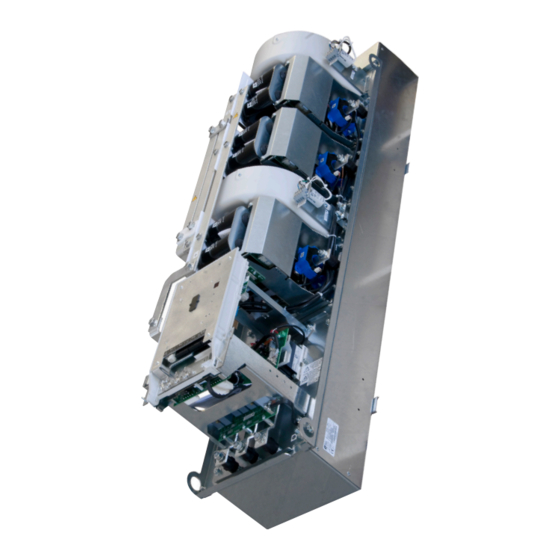
- Page 1 Installation guide POWERDRIVE MD2CS 60T to 570T 270TH to 500TH High-power IP00 drive solution Reference : 4946 - 2017.12 / c...
- Page 2 NOTE NOTE LEROY-SOMER reserves the right to modify the characteristics of its products at any time in order to incorporate the latest technological developments. The information contained in this document is therefore liable to be changed without notice. WARNING For the user’s own safety, this variable speed drive must be connected to an approved earth ( terminal).
- Page 3 SAFETY AND OPERATING INSTRUCTIONS FOR VARIABLE SPEED DRIVES SAFETY AND OPERATING INSTRUCTIONS FOR VARIABLE SPEED DRIVES (In accordance with the low voltage directive 2014/35/EU) Throughout the manual, this symbol warns of consequences which can arise from inappropriate use of the drive, since electrical risks can lead to material or physical damage as well as constituting a fire hazard.
- Page 4 FOREWORD This manual describes the installation of POWERDRIVE MD2CS variable speed drives. It also gives details of all its options and extensions which the user may choose to suit his requirements. POWERDRIVE MD2CS Parameter setting Standard Options MDX-Powerscreen MDX- MDX-SOFT •...
-
Page 5: Table Of Contents
CONTENTS 1 - GENERAL INFORMATION ..........................7 1.1 - General ................................ 7 1.2 - Product designation ............................ 7 1.3 - Environmental characteristics ........................7 1.4 - Electrical characteristics ..........................8 1.4.1 - General characteristics............................8 1.4.2 - Electrical characteristics ............................8 1.4.3 - Derating at low frequency ............................ - Page 6 5 - PARAMETER-SETTING INTERFACE AND OPTIONS ..................32 5.1 - Optionnal Parameter setting interfaces ...................... 32 5.1.1 - Location of the drive connectors / ports ....................... 32 5.1.2 - MDX-Powerscreen .............................. 32 5.1.3 - MDX-KEYPAD ..............................33 5.2 - Add-on options ............................34 5.2.1 - Fieldbus modules ..............................
-
Page 7: General Information
GENERAL INFORMATION 1 - GENERAL INFORMATION 1.3 - Environmental characteristics 1.1 - General Characteristic Level The POWERDRIVE MD2CS is a variable speed drive with Protection IP00 very high performance levels that can be used to control: Storage and transport -30°C to +60°C (see section 7.1) - Induction motors without speed sensor (open loop mode temperature select... -
Page 8: Electrical Characteristics
GENERAL INFORMATION 1.4 - Electrical characteristics All work relating to installation, commissioning and maintenance must be carried out by experienced, qualified personnel. 1.4.1 - General characteristics Characteristic Level 3-phase mains supply: 400 V -10% to 480 V +10% ("T" ratings) or Power supply voltage 525 V -10% to 690 V +10% ("TH"... -
Page 9: Derating At Low Frequency
GENERAL INFORMATION 525 V to 690 V 3-phase supply Switching frequency = 3 kHz - ambient temperature ≤ 40°C (35°C with IP54 option) - altitude ≤ 1000 m. Heavy duty Normal duty Rating Imax (60s) Pout at 575 V Pout at 690 V Pout at 575 V Pout at 690 V POWERDRIVE MD2CS... -
Page 10: Derating According To The Temperature And Switching Frequency
GENERAL INFORMATION 1.4.5 - Derating according to the temperature and switching frequency Ambient temperature ≤ 40°C - altitude ≤ 1000 m. Ico (A) POWERDRIVE MD2CS Heavy duty Normal duty rating 2 kHz 3 kHz 4 kHz 5 kHz 6 kHz 2 kHz 3 kHz 4 kHz... - Page 11 GENERAL INFORMATION Ambient temperature ≤ 50°C - altitude ≤ 1000 m. Ico (A) POWERDRIVE MD2CS Heavy duty Normal duty rating 2 kHz 3 kHz 4 kHz 5 kHz 6 kHz 2 kHz 3 kHz 4 kHz 5 kHz 6 kHz 400 V mains supply 100T 120T...
-
Page 12: Mechanical Installation
MECHANICAL INSTALLATION 2 - MECHANICAL INSTALLATION 2.1 - Checks upon receipt • It is the responsibility of the owner or user of the Before installing the POWERDRIVE MD2CS, check that: POWERDRIVE MD2CS ensure that - The drive has not been damaged during transport installation, operation and maintenance of the drive and - The information on the nameplate is compatible with the its options comply with legislation relating to the safety... -
Page 13: Dimensions And Weight
MECHANICAL INSTALLATION 2.3 - Dimensions and weight 2.3.1 - Drive ratings 60T to 150T Dimensions in mm POWERDRIVE MD2CS rating 100T 120T 150T A (mm) B (mm) 210.5 247.5 Weight (kg) POWERDRIVE MD2CS Installation guide 4946 - 2017.12 / c... -
Page 14: Drive Ratings 180T To 270T
MECHANICAL INSTALLATION 2.3.2 - Drive ratings 180T to 270T Dimensions in mm POWERDRIVE MD2CS rating 180T 220T 270T Weight (kg) POWERDRIVE MD2CS Installation guide 4946 - 2017.12 / c... -
Page 15: Drive Ratings 340T To 570T And 270Th To 500Th
MECHANICAL INSTALLATION 2.3.3 - Drive ratings 340T to 570T and 270TH to 500TH Dimensions in mm POWERDRIVE MD2CS rating 340T 400T 470T 570T 270TH 340TH 400TH 500TH Côte A Weight (kg) POWERDRIVE MD2CS Installation guide 4946 - 2017.12 / c... -
Page 16: Installation
MECHANICAL INSTALLATION 2.4 - Installation 2.4.2 - Air flow 2.4.1 - General Comply with the min./max. dimensions of the ventilation grids POWERDRIVE MD2CS drives are IP00 protection given on the diagrams below (applicable to a single drive). products, designed to be installed in a cabinet with Ensure that the air intakes and outlets on the cabinet are limit access to only habilited and trained personnel. -
Page 17: Temperature
MECHANICAL INSTALLATION 2.5 - Drive losses To ensure correct operation of the drive, it is essential to respect dimensions below. Losses according to the switching frequency Losses (kW) Rating 72mm 2 kHz 3 kHz 4 kHz 5 kHz 6 kHz 28 <... -
Page 18: Connections
CONNECTIONS 3 - CONNECTIONS 3.1 - Power connections • All connections work must be performed by 3.1.1 - Electronics and forced ventilation qualified electricians in accordance with the laws in power supply force in the country in which the drive is installed. This includes earthing to ensure that no directly accessible The control electronics and forced ventilation units are part of the drive can be at the mains voltage or any other... -
Page 19: Location Of Power Terminal Blocks And Recommanded Cabling
CONNECTIONS 3.1.3 - Location of power terminal blocks and recommanded cabling 3.1.3.1 - Ratings 60T to 150T DC - PE 230V 50/60Hz DC + 200VA Connections for braking option See §5.6 230V / 50Hz DO NOT CONNECT EARTH / GROUND * aR fuses according to §... - Page 20 CONNECTIONS 3.1.3.2 - Ratings 180T to 270T PE 230Vac 50/60Hz 200VA PE 230Vac 50/60Hz 200VA DC - Connections for braking option See §5.6 DC + 230V / 50Hz * aR fuses DO NOT CONNECT EARTH / GROUND according to § 3.1.1 230Vac 50/60Hz 100VA...
- Page 21 CONNECTIONS 3.1.3.3 - Ratings 340T to 570T and 270TH to 500TH Rectifier to DC bus link (see §1.4.3) • 1x150mm² for 340T and 400T • 2x150mm² for 470T and 570T • 1x150mm² for 270TH and 500TH PE 230Vac 50/60Hz 4x 250VA DC - DC + Connections for...
-
Page 22: Cables And Fuses
CONNECTIONS 3.1.4 - Cables and fuses • It is the responsibility of the user to connect and provide protection for the POWERDRIVE MD2CS in accordance with the current legislation and regulations in the country of use. This is particularly important with regard to the size of the cables, the type and rating of fuses, the earth or ground connection, powering down, acknowledging trips, isolation and protection against overcurrents. - Page 23 CONNECTIONS Mains power supply Motor 525 V POWERDRIVE rating Fuses (1) Cable cross-section Cable cross- (mm²) Ico (A) section Class J Gg type (mm²) (4) type (UL) Heavy 3x95 + PE(1) 3x95 + PE(1) 270TH Normal 3x120 + PE(1) 3x150 + PE(1) Heavy 3x120 + PE(1) 3x150 + PE(1)
-
Page 24: Connection Of The Control
CONNECTIONS 3.2 - Connection of the control AI1+ Differential analog input 1 (+) AI1- Differential analog input 1 (-) • The POWERDRIVE MD2CS inputs have a positive logic configuration. Using a drive with a control system Factory setting 0-10V speed reference which has a different control logic may cause unexpedted ±... - Page 25 CONNECTIONS Analog output Digital output Factory setting 4-20 mA motor current signal Factory setting Zero speed Bipolar analog voltage in common Characteristic Open collector Output type mode or unipolar current in Absolute maximum voltage + 30 V/0 V common mode Overload current 150 mA Resolution...
-
Page 26: Factory Configuration Of Control Terminal Blocks
CONNECTIONS 3.2.3 - Factory configuration of control • Modification of the Run/Stop control logic terminal blocks - For "3-wire" control (jog Run/Stop): Nota : For more details on the parameters, please refer to the commissioning manual ref.4617 Run FWD Stop +10V ref 0-10 V +24V ref... -
Page 27: Sto-1/Sto-2 Inputs: Safe Torque Off Function
CONNECTIONS 3.3 - STO-1/STO-2 inputs: Safe Torque 3.3.1 - Single channel locking (SIL1 - PLb) Off function 3-phase AC power supply, in accordance with safety standard IEC/EN 62061: 2005 and EN/ISO 13849-1: 2006 - Single The STO-1 and STO-2 inputs are safety inputs that can be channel locking (SIL1 - PLb). -
Page 28: General Emc - Harmonics - Mains Interference
GENERAL EMC - HARMONICS - MAINS INTERFERENCE 4 - GENERAL EMC - HARMONICS - 4.2 - Radio-frequency interference: Immunity MAINS INTERFERENCE 4.2.1 - General The power structure of frequency inverters leads to the occurrence of two types of phenomenom : The immunity level of a device is defined by its ability to - Low-frequency harmonics fed back to the mains supply operate in an environment which is contaminated by external... -
Page 29: Mains Supply
GENERAL EMC - HARMONICS - MAINS INTERFERENCE 4.4 - Mains supply 4.4.3 - Unbalanced power supply 4.4.1 - General Similar to what is observed on an electric motor, the line current imbalance of a drive operating on an unbalanced Each industrial power supply has its own intrinsic mains supply may be several times the value of the characteristics (short-circuit capability, voltage value and voltage imbalance measured on the power supply. -
Page 30: Basic Precautions For Installation
GENERAL EMC - HARMONICS - MAINS INTERFERENCE 4.5 - Basic precautions for installation These should be taken into account when wiring the 4.5.2 - Wiring outside the cabinet POWERDRIVE MD2CS and the external components. In 4.5.2.1 - Control wiring each paragraph, they are listed in decreasing order of effect If the control cable needs to run outside the cabinet, use a on correct operation of the installation. -
Page 31: Electromagnetic Compatibility (Emc)
GENERAL EMC - HARMONICS - MAINS INTERFERENCE 4.6 - Electromagnetic compatibility (EMC) CAUTION: Conformity of the drive is only assured when the mechanical and electrical installation instructions described in this manual are adhered to. Immunity Standard Description Application Conformity IEC 61000-4-2 Electrostatic discharges Product casing Level 3 (industrial) -
Page 32: Parameter-Setting Interface And Options
PARAMETER-SETTING INTERFACE AND OPTIONS 5 - PARAMETER-SETTING INTERFACE AND OPTIONS 5.1.2 - MDX-Powerscreen 5.1 - Optionnal Parameter setting • General interfaces The POWERSCREEN interface is a touch screen which can be used to access various menus to setup and supervise the 5.1.1 - Location of the drive connectors / ports drive. -
Page 33: Mdx-Keypad
PARAMETER-SETTING INTERFACE AND OPTIONS • Architecture Ref. Function From the welcome screen, press the button to access the 3-line backlit LCD display indicating: main page of the parameter-setting interface, consisting of 5 - The drive operating status and its main data touch-sensitive buttons: - The main adjustment parameters via a "Quick parameter setting"... -
Page 34: Add-On Options
PARAMETER-SETTING INTERFACE AND OPTIONS 5.2 - Add-on options 5.2.2 - Speed feedback options The control board is designed to be plugged with various optional modules. Several options can be combined: • Fieldbus (see section 5.2.1) • Speed feedback (see section 5.2.2) •... -
Page 35: Rfi Filters
PARAMETER-SETTING INTERFACE AND OPTIONS 5.4 - RFI filters 5.4.2 - Weight and dimensions • FN 3359 HV-180 and FN 3359 HV-250 5.4.1 - General The use of RFI filters contributes to a reduction in the emission levels of radio-frequency signals (See §4.6). Depending on the drive used, install the RFI filter recommended in the table below between the mains and the drive input. -
Page 36: Mains Chokes
PARAMETER-SETTING INTERFACE AND OPTIONS 5.5 - Mains chokes 5.6 - Associated braking module and resistors POWERDRIVE MD2CS must be connected to an AC line reactor. Braking phases occur when energy is sent back from the motor to the drive. Without an additional device, the maximum Choke power that POWERDRIVE MD2CS can absorb is limited to its Rating... -
Page 37: Braking Resistors
PARAMETER-SETTING INTERFACE AND OPTIONS 5.6.2 - Braking resistors • Before installing a braking resistor, make sure that its presence does not constitute a fire hazard. • A braking resistor must be mounted outside the cabinet, as close as possible. Ensure that it is built into an earthed ventilated metal case, to avoid any direct contact. -
Page 38: Trips - Diagnostics
TRIPS - DIAGNOSTICS 6 - TRIPS - DIAGNOSTICS 6.3 - Tripping on a safetrip If the drive trips, the drive output bridge is inactive, and the 6.1 - Safety notice drive no longer controls the motor. When a trip is active, the LEDs present on the control board The user must not attempt to repair the drive display alternately "t.r."... - Page 39 TRIPS - DIAGNOSTICS Parameter- setting interface Reason for trip Solution name • Check the braking resistor wiring and insulation level. Braking IGBT transistor overcurrent • Make sure that the resistor ohmic value is compatible with Brak. IGBT the MD-TF option used. This trip cannot be reset for a period of 10 seconds.
- Page 40 TRIPS - DIAGNOSTICS Parameter- setting interface Reason for trip Solution name Opening of the PTC input of the PX1 • Check the ambient temperature around the motor. terminal block or T1 and T2 inputs of the • Check that the motor current is less than the stated current. Motor PTC MDX-ENCODER option •...
- Page 41 TRIPS - DIAGNOSTICS Parameter- setting interface Reason for trip Solution name The DO3 output load current (MDX-I/O DO3 MDX-I/O Check that DO3 is not short-circuited. over ld option) is >200 mA Communication problem between the drive Check the MDX-I/O option mounting. MDX-I/O link and the MDX-I/O option Not used...
-
Page 42: Maintenance
MAINTENANCE 7 - MAINTENANCE If the drive has been stored for more than 36 months, the • All work relating to installation, commissioning capacitors must be reformed. maintenance must carried This consists of gradually applying a DC voltage to the banks experienced, qualified personnel. -
Page 43: Power Modules
MAINTENANCE 7.3.3 - Power modules • Rating 180T to 270T • Rectifier module Rating LS code 60T - 75T MPRB 100T - 120T MPRC 150T RDMPRD 180 T- 220T MPRE 270T RDMPRF 340T - 470T LSRDG 570T LSRDH 270TH to 500TH LSRDG 690V •... - Page 44 IMP 297 NO 637 Moteurs Leroy-Somer Headquarter: Boulevard Marcellin Leroy - CS 10015 16915 ANGOULÊME Cedex 9 Limited company with capital of 65,800,512 € RCS Angoulême 338 567 258 www.leroy-somer.com...
Need help?
Do you have a question about the Leroy-Somer POWERDRIVE MD2CS and is the answer not in the manual?
Questions and answers