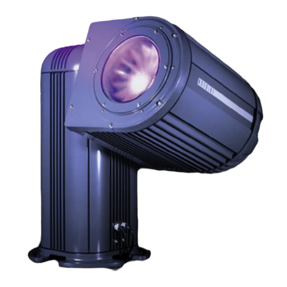
ETC Irideon AR500 Disassembly Instructions
Exterior wash luminaire
Hide thumbs
Also See for Irideon AR500:
- Owner's manual (146 pages) ,
- Installation manual (28 pages) ,
- Troubleshooting manual (3 pages)
Table of Contents
Advertisement
Quick Links
Important Note
Important Note
Important Note
Important Note
Units are static sensitive. Observe care when installing/servicing. Retain original packaging for
returns/service.
Stanchion
Stanchion
Stanchion
Stanchion
Note: Make sure gaskets make a good seal whenever changing out parts.
Note: Make sure gaskets make a good seal whenever changing out parts.
Note: Make sure gaskets make a good seal whenever changing out parts.
Note: Make sure gaskets make a good seal whenever changing out parts.
Ballast Plate
Ballast Plate
Ballast Plate
Ballast Plate
•
Different Ballasts for different voltages
Composer Control Protocol Plate
Composer Control Protocol Plate
Composer Control Protocol Plate
Composer Control Protocol Plate
•
CPU
•
Address Wheels √ ≈00∆ is self-test
•
LED»s √ Green is data, yellow is power
•
Comm protection PCB
•
Power supply
•
Fuse for Power to CPU
•
Resistor
DMX512 Control Plate
DMX512 Control Plate
DMX512 Control Plate
DMX512 Control Plate
•
Address Board √ Self-tests in the 900 range
•
Power Supply √ 2 fuses
•
CPU √ 2 fuses
•
Power to board
•
Data
•
Igniter (remote stanchion)
•
Remove cover from remote foot (loosen screws in diagonal pattern)
•
Disconnect AC from T-block
•
Remove screws from Igniter mounting plate and pull out igniter
IRID 110
AR500 Disassembly Instructions
AR500 DISASSEMBLY INSTRUCTIONS
AR500 DISASSEMBLY INSTRUCTIONS
AR500 DISASSEMBLY INSTRUCTIONS
AR500 DISASSEMBLY INSTRUCTIONS
IRID 110
IRID 110
IRID 110
IRID 110
Revised: 7/27/2000
Page 1 of 2
Advertisement
Table of Contents

Subscribe to Our Youtube Channel
Related Manuals for ETC Irideon AR500


Summary of Contents for ETC Irideon AR500
- Page 1 IRID 110 IRID 110 IRID 110 IRID 110 AR500 DISASSEMBLY INSTRUCTIONS AR500 DISASSEMBLY INSTRUCTIONS AR500 DISASSEMBLY INSTRUCTIONS AR500 DISASSEMBLY INSTRUCTIONS Important Note Important Note Important Note Important Note Units are static sensitive. Observe care when installing/servicing. Retain original packaging for returns/service.
- Page 2 Head Head Head Head Front and Back covers Front and Back covers Front and Back covers Front and Back covers • Loosen 6 screws and remove head enclosure front cover • Loosen 6 screws and remove head enclosure rear cover •...
Need help?
Do you have a question about the Irideon AR500 and is the answer not in the manual?
Questions and answers