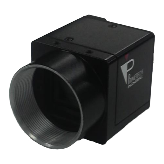
Summary of Contents for Primetech PXA30SHE
- Page 1 PRIMETECH ENGINEERING RoHS Operation Manual Ver. 1.1 Analog Black & White CCD Camera TV format Model PXA30SHE (with ND filter) PXA35SHE (no ND filter) Primetech Engineering Corp. 1/30...
- Page 2 PRIMETECH ENGINEERING Thank you for your purchase of the Primetech Engineering product. We ensure that you will enjoy this and other products from Primetech Engineering for many years. Keep this manual and warranty card handy for future reference. To ensure the safe use of this product, carefully read the warnings and cautions provided below prior to use: Warning Failure to follow the warning message may result in death or serious injury.
- Page 3 PRIMETECH ENGINEERING Primetech Engineering shall assume no responsibility for the following under any circumstance: ■ Loss arising from fire, earthquake, a man-made disaster or an act of God; willful or accidental misuse of the product; or use of the product by a third party in an abnormal manner;...
- Page 4 PRIMETECH ENGINEERING Revision History Revision Date of revision Description of change 2019/03/14 Released the initial version. 2020/07/15 Correction of errors 4/30...
-
Page 5: Table Of Contents
PRIMETECH ENGINEERING Table of Contents Overview ....................................6 1.1. Characteristics ................................6 System Configuration ................................7 Connection Diagram ................................8 Specifications of Camera Parts ............................. 9 4.1. Front/Top/Bottom ................................9 4.2. Rear panel ..................................10 4.3. Pin assignment for VIDEO OUT/DC IN/SYNC terminal ..................... 11 4.4. -
Page 6: Overview
PRIMETECH ENGINEERING 1. Overview This operation manual describes functions and procedures for the industrial analog camera (B/W). 1.1. Characteristics • Diverse mode setting The following settings can be used by toggling the switch on the rear panel. • Gain control •... -
Page 7: System Configuration
PRIMETECH ENGINEERING 2. System Configuration <Camera module> <Camera cable> <C-mount lens> <Tripod adaptor> 7/30... -
Page 8: Connection Diagram
PRIMETECH ENGINEERING 3. Connection Diagram C-mount lens Camera module Camera cable <Camera adaptor, etc.> <Tripod adaptor> 8/30... -
Page 9: Specifications Of Camera Parts
PRIMETECH ENGINEERING 4. Specifications of Camera Parts 4.1. Front/Top/Bottom [1] Lens mount (C-mount) [2] Auxiliary screw hole for fixing camera (top) [3] Auxiliary screw holes for fixing camera/ screw holes for installing tripod (bottom) [4] Reference screws hole for fixing... -
Page 10: Rear Panel
PRIMETECH ENGINEERING 4.2. Rear panel [2] DIP switch for setting shutter speed and mode [1] VIDEO OUT/DC IN/SYNC (video output/DC power/ sync signal input/output) terminal (12-pin connector) [5] 75Ω termination switch [3] VD/HD signal input/output switch [4] Manual gain control knob Caution Turn off the module before setting switches. -
Page 11: Pin Assignment For Video Out/Dc In/Sync Terminal
PRIMETECH ENGINEERING 4.3. Pin assignment for VIDEO OUT/DC IN/SYNC (video output/DC power/synchronizing signal input/output) terminal Rear panel Pin assignment for VIDEO OUT/DC IN/SYNC (Video output/DC power/synchronizing signal input/output) terminal Pin No. Camera synchronizing External synchronizing Restart/reset Externally triggered signal output... -
Page 12: Input Phase Specifications For External Vd/Hd Signal
PRIMETECH ENGINEERING 4.4. Input phase specifications for external VD/HD signal Set the phase relationship for external VD and HD signals as shown in the above figure. Note that inputs other than those specified above can cause unstable internal reset. For normal shutter mode... -
Page 13: External Trigger Shutter Speed Setting According To Trigger Pulse Width
PRIMETECH ENGINEERING 4.7. Externally triggered shutter speed setting according to trigger pulse width Set all DIP switches 1 to 4 on the rear panel to "0". Setting the trigger pulse width within the range from 2 s to 250 ms will achieve an arbitrary shutter speed. -
Page 14: Normal Shutter Mode
PRIMETECH ENGINEERING 5. Normal Shutter Mode This mode is to clearly capture high-speed moving objects with a shutter function using continuously obtained video signals. Setting of the DIP switches on the rear panel 1/125 1/250 1/500 1/1000 Flickerless 1/2000 1/4000... -
Page 15: External Trigger Shutter
PRIMETECH ENGINEERING 6. External Triggered Shutter Inputting a trigger from an external device will enable capturing of high-speed moving objects at a correct position. Set DIP switches 6, 7, and 8 on the rear panel to those specified for mode 1 or 2. (See the figures on the following pages.) When the trigger pulse width is set to 1/3 s or more, the output is switched to a normal video signal. - Page 16 PRIMETECH ENGINEERING Setting with DIP switches on the rear panel Mode 2 (Reset mode) Cautions • DIP switch 5, 9, 0 is optional. 16/30...
-
Page 17: Restart/Reset
PRIMETECH ENGINEERING 7. Restart/reset By inputting restart/reset signals (VD/HD) from an external device, you can obtain information for one screen at an arbitrary timing. To specify this mode, set DIP switches 6, 7, and 8 on the rear panel of the camera as shown in the following figure. - Page 18 PRIMETECH ENGINEERING 18/30...
-
Page 19: Timing Chart For Individual Modes
PRIMETECH ENGINEERING 8. Timing Chart for Individual Modes 8.1. Mode 1 19/30... - Page 20 PRIMETECH ENGINEERING 20/30...
- Page 21 PRIMETECH ENGINEERING 21/30...
- Page 22 PRIMETECH ENGINEERING 22/30...
- Page 23 PRIMETECH ENGINEERING 23/30...
- Page 24 PRIMETECH ENGINEERING 24/30...
-
Page 25: Mode 2
PRIMETECH ENGINEERING 8.2. Mode 2 25/30... - Page 26 PRIMETECH ENGINEERING 26/30...
-
Page 27: Specifications
50 ns or less Jitter Scanning method 2:1 Interlace/Non Interlace (at External Sync input) Sensitivity PXA30SHE: 400 lx (gain:Min, F4.0, gamma:ON, shutter:OFF) PXA35SHE: 400lx (gain:Min, F11.0, gamma:ON, shutter:OFF) S/N ratio 60dB Minimum illumination PXA30SHE: 0.3 lx (gain:Max, F1.4, gamma:ON, shutter:OFF) PXA35SHE: 0.06lx (gain:Max, F1.4, gamma:ON, shutter:OFF) -
Page 28: Relative Spectral Sensitivity Characteristics
PRIMETECH ENGINEERING 9.1. Relative spectral sensitivity characteristics 28/30... -
Page 29: External Dimensions
PRIMETECH ENGINEERING External Dimensions Units: mm 29/30... - Page 30 Thus we assume no responsibility whatsoever for any violation resulting from such use. Contact: Primetech Engineering Corp. 1-3-25, Koishikawa, Bunkyo-ku, Tokyo 112-0002 Tel.


Need help?
Do you have a question about the PXA30SHE and is the answer not in the manual?
Questions and answers