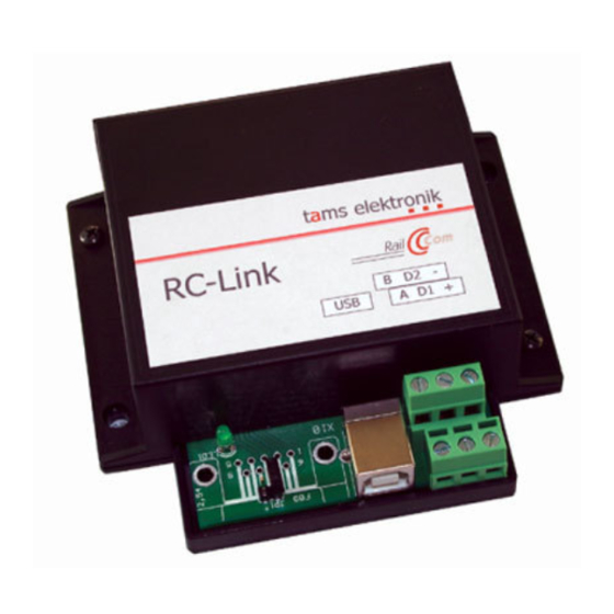
Summary of Contents for tams elektronik RC-Link
- Page 1 Manual RC-Link Item no. 45-02257 | 45-02267 RailCom PC Interface tams elektronik n n n...
-
Page 2: Table Of Contents
RC-Link Table of contents 1. Getting started ................3 2. Safety instructions...............5 3. Background information: RailCom..........6 4. Operating mode of the RC-Link............8 5. Technical specifications..............10 6. Connections and funcitonal tests..........11 7. Programming the detectors´ addresses........15 8. Check list for troubleshooting.............16 9. Guarantee bond................18 10. -
Page 3: Getting Started
Any other use is inappropriate and invalidates any guarantees. The RC-Link should not be mounted by children under the age of 14. Reading, understanding and following the instructions in this manual are mandatory for the user. - Page 4 English RC-Link Required materials In order to connect the device you need wire. Recommend diameters: data bus: > 0,1 mm². It is recommended to use twin wire (e.g. LiYz, 2x0,19 mm², red-brown, item no. 73-30037); connections to the interface´s power supply: > 0,25 mm².
-
Page 5: Safety Instructions
RC-Link English 2. Safety instructions Mechanical hazards Cut wires can have sharp ends and can cause serious injuries. Watch out for sharp edges when you pick up the PCB. Visibly damaged parts can cause unpredictable danger. Do not use damaged parts: recycle and replace them with new ones. -
Page 6: Background Information: Railcom
PC interfaces. That is the reason why the use of detectors, display devices and PC interfaces of one manufacturer is mandatory. The data bus used by Tams Elektronik for the communication between detectors, display devices and PC interfaces allows you ... - Page 7 24-fold display device RCA-24, displaying the data from all 13 track sections, one RailCom PC interface RC-Link. Bus line For technical reasons, there are two wires with a diameter of minimum 0,10 mm² mandatory as a bus line for the communication between detectors, display devices and PC interfaces (lines A and B).
-
Page 8: Operating Mode Of The Rc-Link
PC in this case, failures in operational procedures and accidents could occur. In order to meet with this problem, the RC-Link checks via a port for the connection to the rails if a track voltage is applied. Only when a track voltage is applied, current disengaged reports are transferred to the PC. - Page 9 When performing functional tests connecting the RC-Link to the rails may involve a high effort. For that reasons it is possible to do without connecting the RC-Link to the rails as well. With an open track port (and thus supposed broken down track voltage) the RC-Link however supresses the transfer of disengaged reports, which is unwelcome in this constellation.
-
Page 10: Technical Specifications
English RC-Link 5. Technical specifications Attention: As a power supply for the RC-Link you should not use the transformer supplying the digital control. If possible you should use a separate transformer supplying only the RailCom components on your layout. Supply voltage... -
Page 11: Connections And Funcitonal Tests
RC-Link English 6. Connections and funcitonal tests Fig. 2: Connection RC-Link with USB interface. Fig. 3: Connection RC-Link with V.24 interface. Page 11... - Page 12 It is recommended to make the connections and functional tests step- by-step according to the manual. Step 1: Connection to the PC Connect the RC-Link to the PC with the USB or V.24 cable enclosed in the package. Step 2: Connecting the power supply Attention: As a power supply for the RC-Link you should not use the transformer supplying the digital control.
- Page 13 PC from the PC – and click to the field "Sys-Info". The numbers of the software and the hardware version of the RC-Link are shown on the monitor. This shows you the communication between PC and RC-Link is working.
- Page 14 You can assign a maximum of 24 detectors (e.g. RCD-1, RCD-2 or RCD- 8) to the RC-Link. As the data transfer between the detectors on the one side and the display devices and PC interfaces on the other side is run on a Tams specific data bus, you cannot connect devices from other manufacturers to the data bus.
-
Page 15: Programming The Detectors´ Addresses
7. Programming the detectors´ addresses You can use the PC to program the addresses of the connected detectors (no. 1 to 24) via the RC-Link. You need a special software for that (e.g. PC-RC on the included CD). Proceed as follows: ... -
Page 16: Check List For Troubleshooting
Possible cause: When installing the software another interface has been choosen other than the one connected with the RC-Link. à If necessary alter the interface at the PC. Possible cause: The connection A of the RC-Link is connected to the connection B of the detector (or the other way round). - Page 17 RC-Link English Hotline: If problems with your module occur, our hotline is pleased to help you (mail address on the last page). Repairs: You can send in a defective module for repair (address on the last page). In case of guarantee the repair is free of charge for you.
-
Page 18: Guarantee Bond
English RC-Link 9. Guarantee bond For this product we issue voluntarily a guarantee of 2 years from the date of purchase by the first customer, but in maximum 3 years after the end of series production. The first customer is the consumer first... -
Page 19: Eu Declaration Of Conformity
This product conforms with the EC-directive 2012/19/EG on waste electrical and electronic equipment (WEEE). The Tams Elektronik GmbH is registered with the WEEE-no. DE 37847206, according to. § 6 sect. 2 of the German electro regulations from the responsible authority for the disposal of used electro equipment. - Page 20 Information and tips: http://www.tams-online.de Warranty and service: Tams Elektronik GmbH Fuhrberger Straße 4 DE-30625 Hannover fon: +49 (0)511 / 55 60 60 fax: +49 (0)511 / 55 61 61 e-mail: modellbahn@tams-online.de...


Need help?
Do you have a question about the RC-Link and is the answer not in the manual?
Questions and answers