Nortel Meridian 1 Manual
European digital telephones
Hide thumbs
Also See for Meridian 1:
- Manual (1121 pages) ,
- Planning and installation manual (612 pages) ,
- Planning, installation and operating instructions (556 pages)
Table of Contents
Advertisement
Meridian 1
Meridian 1 European Digital Telephones
Document Number: 553-3001-114
Document Release: Standard 3.00
Date: April 2000
Year Publish FCC TM
Copyright © 1997–2000 Nortel Networks
All Rights Reserved
Printed in Canada
Information is subject to change without notice. Nortel Networks reserves the right to make changes in design
or components as progress in engineering and manufacturing may warrant. This equipment has been tested
and found to comply with the limits for a Class A digital device pursuant to Part 15 of the FCC rules, and the
radio interference regulations of Industry Canada. These limits are designed to provide reasonable protection
against harmful interference when the equipment is operated in a commercial environment. This equipment
generates, uses and can radiate radio frequency energy, and if not installed and used in accordance with the
instruction manual, may cause harmful interference to radio communications. Operation of this equipment in a
residential area is likely to cause harmful interference in which case the user will be required to correct the
interference at their own expense.
SL-1 and Meridian 1 are trademarks of Nortel Networks.
Meridian 1 European Digital Telephones
Advertisement
Table of Contents

Related Manuals for Nortel Meridian 1


Summary of Contents for Nortel Meridian 1
- Page 1 All Rights Reserved Printed in Canada Information is subject to change without notice. Nortel Networks reserves the right to make changes in design or components as progress in engineering and manufacturing may warrant. This equipment has been tested and found to comply with the limits for a Class A digital device pursuant to Part 15 of the FCC rules, and the radio interference regulations of Industry Canada.
- Page 3 Revision history April 2000 Standard 3.00. This is a global document and is up-issued for X11 Release 25.0x. February 1997 Standard, release 2.00 based on changes in product. October 1996 Standard, release 1.00 for Gate 2A. Meridian 1 European Digital Telephones...
- Page 4 Page 4 of 46 Revision History 553-3001-114 Standard 3.00 April 2000...
-
Page 5: Table Of Contents
Index ........Meridian 1 European Digital Telephones... - Page 6 Page 6 of 46 Contents 553-3001-114 Standard 3.00 April 2000...
-
Page 7: Preface
Page 7 of 46 Preface This document is a global document. Contact your system supplier or your Nortel Networks representative to verify that the hardware and software described is supported in your area. This guide provides feature, add-on module, and specification information for Meridian digital telephones. - Page 8 Page 8 of 46 Preface 553-3001-114 Standard 3.00 April 2000...
-
Page 9: Meridian Digital Telephones
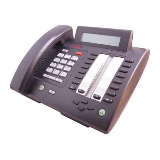
These telephones communicate with the Meridian 1 using digital transmission over standard twisted-pair wiring. They interface with the Meridian 1 using the Integrated Services Digital Line Card (ISDLC) or the eXtended Digital Line Card (XDLC). Meridian digital telephones are connected to the system through a two-wire loop carrying two independent 64 kbs PCM channels with associated signaling channels. - Page 10 Page 10 of 46 Meridian digital telephones Figure 1 The Location and Function of Buttons on the Meridian digital telephone Program Key† LCD Indicators Display Module† Feature Keys Release (Rls) Key Message Waiting Indicator Hold Key Speaker Speaker/Mute LED Speaker Key Mute Key Edit Key* Callers List Key*...
- Page 11 Dedicated Release and Hold keys • Message Waiting and Speaker/Mute Indicators • Headset Socket • 2 x 24 character display • 20 Feature keys including: — Store/program key — 13 system programmable keys — Handsfree/speaker key — Mute key Meridian 1 European Digital Telephones...
- Page 12 Page 12 of 46 Meridian digital telephones — Directory key — Caller’s List key — Edit key — Delete key • Volume control for: — Handset/Headset — Ringing Tone — Buzz Tone — On-Hook dialling and Group Listening — Handsfree •...
- Page 13 Dedicated Release and Hold keys • Message Waiting and Speaker/Mute Indicators • Headset Socket • 2 x 24 character display • 10 Feature keys including: — Program key — 7 system programmable keys — Speaker key — Mute key Meridian 1 European Digital Telephones...
- Page 14 Page 14 of 46 Meridian digital telephones — Volume control for: — Handset/Headset — Ringing Tone — Buzz Tone — On-Hook dialling and Group Listening — Handsfree • Support for the following set options: — MCA data option to provide integrated voice and data —...
- Page 15 Message Waiting and Mute Indicators • 10 Feature System Programmable keys including: — 8 system programmable keys — Mute key — Speaker key • Volume control for: — Handset — Ringing Tone — Buzz Tone Meridian 1 European Digital Telephones...
- Page 16 Page 16 of 46 Meridian digital telephones — On-Hook dialling and Group Listening • Support for the following terminal options: — MCA data option to provide integrated voice and data — External Alerter for high ambient noise environments • Wall mount ability •...
-
Page 17: Meridian Digital Telephones Used With A Headset
500 micro amps. The differential input impedance is 10K ohms. Connects to pins 2 and 5 of the headset jack. Receive interface: single ended output with output impedance of 180 ohms. Connects to pins 3 and 4 of the headset jack. Meridian 1 European Digital Telephones... -
Page 18: Physical Characteristics
Page 18 of 46 Meridian digital telephones Physical characteristics Fixed keys (same for all three models) • Hold: By pressing the hold key, you can put an active call on hold. Return to the caller by pressing the extension key beside the flashing LCD indicator. - Page 19 In Handsfree mode, the user (or group of users) uses both the handsfree microphone and speaker. Meridian 1 European Digital Telephones...
- Page 20 Page 20 of 46 Meridian digital telephones Note 2: Group listening is switched on or off under the program key option *1. (M3820 and M3310 only) Additional feature keys Message Waiting lamp key. Each telephone has a red message waiting LED just above the hold and Rls keys that lights to indicate a message is waiting.
-
Page 21: Software Requirements
Feature keys Handsfree microphone Optional hardware available: Key Expansion Module Meridian Communications Adapter (MCA) External alerter interface Brandline insert Note: In this table, x indicates available features for the telephone type listed in the top row. Meridian 1 European Digital Telephones... -
Page 22: External Alerter Interface
Page 22 of 46 Meridian digital telephones External Alerter interface The External Alerter Board provides an interface to standard remote ringing devices, such as a ringing unit, installed in a location separate from the telephone. The External Alerter interface is not the remote ringer itself, but provides access to standard, off-the-shelf remote ringing devices. - Page 23 If Group Listening is 11 NUL denied (CLS HFD), 12 NUL Key 15 is also 13 NUL programmed as NUL. 14 NUL If Group Listening is denied (CLS HFD), Key 15 is also programmed as NUL. Meridian 1 European Digital Telephones...
- Page 24 Page 24 of 46 Meridian digital telephones Figure 5 M3110 Key Designation 553-3001-114 Standard 3.00 April 2000...
- Page 25 Handsfree Allowed (Denied) 08 NUL Keys 8-14 09 NUL programmed as NUL. 10 NUL If Handsfree is 11 NUL denied (CLS HFD), 12 NUL Key 15 is also 13 NUL programmed as NUL. 14 NUL Meridian 1 European Digital Telephones...
- Page 26 Page 26 of 46 Meridian digital telephones Figure 6 M3310 Key Designations 553-3001-114 Standard 3.00 April 2000...
- Page 27 Key 15 is also configured as an programmed as NUL. SCR key with the same DN as key 0. For MARP to operate with short hunt configured, Key 01 must be configured as the MARP key. Meridian 1 European Digital Telephones...
- Page 28 Page 28 of 46 Meridian digital telephones Figure 7 M3820 Key Designations Table 6 Overlay 20 Print Routine Prompt Response Comments TYPE 2616 M2616 set model used. M3110 Enter M3310 appropriate set M3820 identifier Or M3+ to get a list of all three set types.
- Page 29 Wallmount/Desktop Position change. For installation of other options (MCA data option, external alerter and key expansion modules) see the section on Add-on modules for Meridian Modular Telephones (NT2K models) in the Telephone and Attendant Console: Installation (553-3001-215). Meridian 1 European Digital Telephones...
- Page 30 Page 30 of 46 Meridian digital telephones Power Board Installation To open the Telephone: Place the telephone, upside-down, on a padded, level surface. Using a #1 Phillips screwdriver, remove the two screws holding the footstand (if fitted). Disconnect and remove all cords including the handset and headset if fitted, from the telephone.
- Page 31 Replace the footstand in the same position and tighten both screws (if previously fitted). Place the telephone back on the desk in the normal operating position. Plug the line cord connector back into the connecting block. Meridian 1 European Digital Telephones...
- Page 32 Page 32 of 46 Meridian digital telephones Figure 8 Power Board Installation 553-3001-114 Standard 3.00 April 2000...
- Page 33 Remove the 2 screws from the telephone footstand (if fitted) to separate the footstand from the telephone. Meridian 1 European Digital Telephones...
- Page 34 Page 34 of 46 Meridian digital telephones Remove the wall mount clip located inside the footstand and insert the clip in the switchhook rest using the holes provided. Rotate the footstand 180 degrees, snap the footstand back into place and tighten the screws.
-
Page 35: Specifications
All the digital telephones are designed to comply with: EN 50082-1:1992 - Electromagnetic Compatibility - Generic immunity standard Part 1: Residential, commercial and light industry. EN 50081-1:1992 - Electromagnetic Compatibility - Generic emissions standard. Generic standard class: Residential, commercial and light industry. Meridian 1 European Digital Telephones... -
Page 36: Line Engineering
Page 36 of 46 Meridian digital telephones Line engineering Meridian digital telephones use twisted pair wiring on transmission lines selected by the rules given in Digital Telephone Line Engineering (553-2201-180). The maximum permissible loop length is 3500 ft. (1067 m), assuming 24 AWG (0.5 mm) standard twisted wire with no bridge taps. -
Page 37: Power Requirements
Note: If a power failure occurs, configurations that require loop power will continue to work only if the system has battery backup. Only those options that require additional power will cease to function. Meridian 1 European Digital Telephones... - Page 38 Page 38 of 46 Meridian digital telephones Table 8 Power requirements, Meridian digital telephones Additional power Telephone type Loop power (Power Supply Board) M3820 Terminal, handsfree, headset, key MCA, External Alerter Interface expansion M3310 Terminal, headset, handsfree MCA, External Alerter Interface M3110 Terminal MCA, External Alerter Interface...
- Page 39 Meridian digital telephones Page 39 of 46 Figure 9 Configuration of local plug-in transformer To IDF Adapter jack Adapter plug 6-conductor line cord from telephone Plug Jack Wall transformer (110 V or 220 V) Adapter 553-1855 Meridian 1 European Digital Telephones...
- Page 40 Page 40 of 46 Meridian digital telephones 120 V transformer The following minimum specifications must be met by this transformer: Input voltage 120 V ac/60 Hz No load output voltage 29 V ac maximum Voltage at rated current 26.7 V ac minimum Rated load current 700 mA 240 V transformer The following minimum specifications have to be met by...
- Page 41 42 V dc, 300 mA isolated, with current limiting output of 1 amp. Figure 10 Closet Power Supply configuration Tip (r) To IDF Ring (g) 6-conductor line cord from telephone Connects to an isolated output Closet Power Supply (Shumway SBI 221-25 or equivalent) 553-1856 Meridian 1 European Digital Telephones...
- Page 42 Page 42 of 46 Meridian digital telephones 553-3001-114 Standard 3.00 April 2000...
-
Page 43: Glossary
Automatic Call Distribution Asynchronous Data Option Class of Service CCOS Controlled Class of Service Call Progress Monitor CPND Calling Party Name Display Data Communications Equipment Digital Line Card Directory Number Meridian 1 European Digital Telephones... - Page 44 Page 44 of 46 Glossary DSIC Digital Set Interface Chip Data Terminal Equipment Electronic Industries Association Federal Communications Commission Intermediate Distribution Frame ISDLC Integrated Services Digital Line Card Liquid Crystal Display Light Emitting Diode (lamp) Main Distribution Frame Meridian Communications Adapter Pulse Code Modulation Terminal Number 553-3001-114 Standard 3.00 April 2000...
-
Page 45: Index
See also ADO (Asynchronous Data Option) data channels, 9 idle state dialing M3820, M3310, M3110 telephones, 20 See also Handsfree operation ISDLC (Integrated Services Digital Line Card), 9 dimensions. See under individual modes of telephones Meridian 1 European Digital Telephones... - Page 46 See also programmable keys line engineering, 36 local alerting tones, 36 M3820, M3310, M3110 telephones TELADAPT snap-in connectors, 40 power requirements telephones. See Meridian 1 telephones M3820, M3310, M3110 tele- temperature and humidity ranges for operations phones , 37 Meridian digital telephones, 35 Meridian 1 telephones tones.
- Page 48 Operation of this equipment in a residential area is likely to cause harmful interference in which case the user will be required to correct the interference at their own expense. SL-1 and Meridian 1 are trademarks of Nortel Networks. Publication number: 553-3001-114 Document release: Standard 3.00...
Need help?
Do you have a question about the Meridian 1 and is the answer not in the manual?
Questions and answers