Table of Contents
Advertisement
Quick Links
Advertisement
Table of Contents

Related Manuals for Optimus ME-200C


Summary of Contents for Optimus ME-200C
-
Page 3: Table Of Contents
CONNECTION..................................8 5.1. Power supply ................................. 8 5.2. Audio and CAN bus connection ............................. 8 5.2.1. CAN Bus and audio connection between ME-200C and COMPACT unit ............9 5.2.2. CAN Bus and audio connection between several ME-200C ................. 9 5.2.3. -
Page 4: Introduction
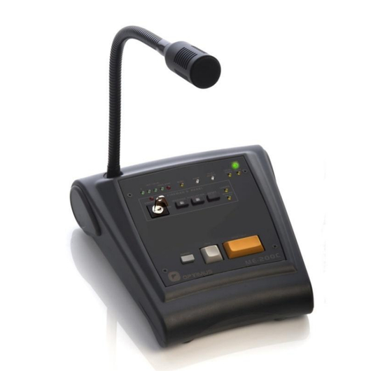
Powered by 24V DC. tone and final tone (Gong). Every COMPACT matrix unit allows connecting 16 units of 3 or 4 tones configurable Gong. ME-200C microphone desks. Repeat Key, for repetition of the last live voice message. 2. FRONT VIEW (1) Microphone (4) WARNING push-button. - Page 5 Microphone desk and ME-200C voice alarm fireman's panel Figure 1 (10) GENERIC FAULT indicator. System alarm indicator. (15) TALK / REPEAT LED. Illuminates when TALK or GONG+TALK is pressed, indicating that you can begin speaking. When the REPEAT key is pressed, it indicates that (11) LOGGED LED.
-
Page 6: Rear View
DIP switch 1. RJ45 SHLD-GND LINK. Allows separating the PIN the connection of several ME-200C microphone desks (up to 8 and the shield of the RJ45 connectors from the ME-200C a maximum of 16) forming a BUS between elements. See internal ground (GND). -
Page 7: Configuration
4. CONFIGURATION Use the DIP switches on the back of the microphone to configure it: DIP switch 1. RJ45 SHLD-GND LINK. Allows separating the PIN 8 and the shield of the RJ45 connectors from the ME-200C internal ground (GND). DIP switches 2 and 3. BUS CAN END. Configure DIP switches 2 and 3 to indicate the position on the CAN bus occupied by the ME- 200C (end element or intermediate element). -
Page 8: Connection
Microphone desk and ME-200C voice alarm fireman's panel 5. CONNECTION 5.1. Power supply The microphone desk should be powered at 24VDC through the DC IN 24V terminal strip on the back plate. Figure 3 24V DC POWER SUPPLY I924UP (Not included) 5.2. -
Page 9: Can Bus And Audio Connection Between Me-200C And Compact Unit
Microphone desk and ME-200C voice alarm fireman's panel 5.2.1. CAN Bus and audio connection between ME-200C and COMPACT unit Figure 5 shows the most common connection To COMPACT unit between an ME-200C and the COMPACT audio To UMX-EA3 card matrix with the UMX-EA3 input card. To facilitate the connection it is recommended to use an Optimus Z-52A patch panel or similar. -
Page 10: Connection Between Me-200C And Compact-E Expansion Unit
ME-200C voice alarm fireman's panel 5.2.3. Connection between ME-200C and COMPACT-E expansion unit Figure 7 To COMPACT-E The CAN communication speed of the ME-200C is 33.3 expansion unit kbit/s. For installation with COMPACT-E expansion units 24V DC To UMX-EA3 card... -
Page 11: Commissioning The Unit
To do this, you need a PC equipped with a network card and connected to the COMPACT matrix, either through a ethernet switch, or directly through a network cable. The PC must have the Call Point software installed. 1. Set the CAN address of the ME-200C and its position in the BUS (end or intermediate element) according to section 4. CONFIGURATIONS. -
Page 12: Operations In Emergency Mode
Microphone desk and ME-200C voice alarm fireman's panel 9. OPERATIONS IN EMERGENCY MODE All the emergency messages (live messages as well as pre-recorded WARNING and EVACUATION messages) will be broadcast to the ASSOCIATED GROUP. The ASSOCIATED GROUP must have been previously configured via the Call Point software. -
Page 13: System Alarms
Microphone desk and ME-200C voice alarm fireman's panel 10. SYSTEM ALARMS The microphone desk incorporates several alarm indicators: LOCAL FAULT indicator: Front yellow LED. Indicates microphone capsule error or communication error with audio matrix. CPU FAULT indicator: Front yellow LED. Illuminates when the microphone desk detects an internal application error (firmware). -
Page 14: Technical Characteristics
500 Ohm 30% (at 1kHz) Material Aluminium 13. SOFTWARE AND FIRMWARE VERSIONS The functionalities described in this user manual are valid for software and firmware versions that are the same or later versions of: ME-200C Firmware COMPACT Firmware Application version 3.1.4877 Linux version 2.6.35.14... -
Page 15: Guarantee
In the event that the guarantee rights do not apply, OPTIMUS S.A. shall duly inform the client. If, within a period of 6 weeks 2. GUARANTEE PROVISIONS...
Need help?
Do you have a question about the ME-200C and is the answer not in the manual?
Questions and answers