
Related Manuals for Keysight Technologies UXG X Series


Summary of Contents for Keysight Technologies UXG X Series
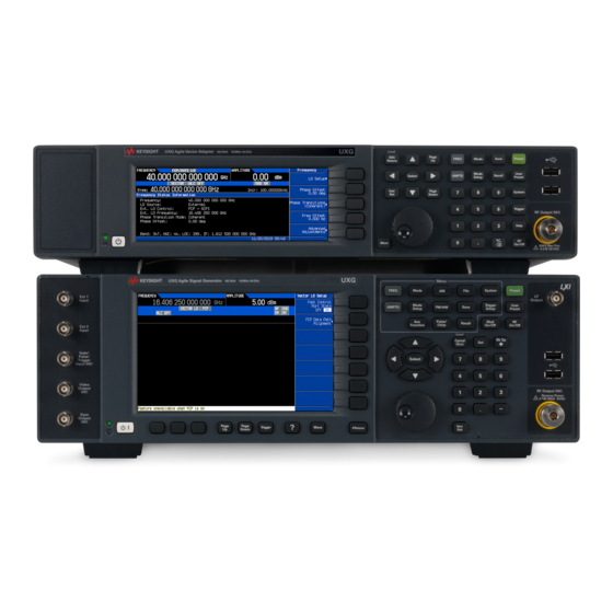
- Page 1 Keysight UXG X-Series Agile Signal Generators Add Option SS4 (Switching Speed) Kit Part Number: N5191-60230 Installation Note...
- Page 2 The information contained in this document is subject to change without notice. Keysight Technologies makes no warranty of any kind with regard to this material, including but not limited to, the implied warranties of merchantability and fitness for a particular purpose.
- Page 3 To Be Performed By: ..... . (X) Keysight Technologies Service Center (X) Personnel Qualified by Keysight Technologies ( ) Customer Estimated Installation Time: .
-
Page 4: Installation Kit Parts List
Add Option SS4 (Switching Speed) Kit Part Numbers: N5191-60230 Installation Kit Parts List Table 1 N5191-60230, for Option 540 Quantity Description Part Number UXG X-Series Agile Signal Generators Add SS4 to Option 540 this note Installation Note Assembly, 40 GHz Doubler, Tested N5191-60335 Entitlement Certificate Tools Required... -
Page 5: Check Signal Generator Functionality
Add Option SS4 (Switching Speed) Kit Part Numbers: N5191-60230 Check Signal Generator Functionality Use the following procedure to confirm that the signal generator powers up and the internal check identifies no errors. The internal check evaluates the operation of the signal generator and returns an error message if it detects a problem. - Page 6 Remove the Outer and Inner Bottom Rear Cover Remove the Outer and Inner Bottom Rear Cover Remove the Outer Cover Refer to Figure 1. Disconnect the power cord. 2. Using a T-20 driver, loosen the screws (1) and remove the strap handles (2) from both sides of the instrument.
- Page 7 Remove the Outer and Inner Bottom Rear Cover Remove the Inner Bottom Rear Cover Refer to Figure 1. Place the signal generator upside down. 2. To remove from the rear bottom cover (1), use a T-10 driver to remove the twelve screws (2) (including two on the rear panel).
- Page 8 Install Option SS4 (Instruments with Front Panel RF Output) Install Option SS4 (Instruments with Front Panel RF Output) Remove Existing A19 40 GHz Doubler 1. Refer to Figure 3. Remove cables W23 and W25. Also disconnect the cable at the location indicated.
- Page 9 Activate Option SS4 Activate Option SS4 1. Turn the signal generator on and allow it to warm up for 5 minutes. 2. Follow the instructions on the Entitlement Certificate to redeem Option SS4. 3. Connect the instrument to the LAN and write down the IP address. 4.
-
Page 10: Verify Signal Generator Calibration
Verify Signal Generator Calibration Verify Signal Generator Calibration 1. Turn the signal generator on and allow it to warm up for 45 minutes. 2. Perform the following adjustment and performance tests, in the order listed, to verify signal generator calibration. Refer to the UXG Family Signal Generators Service Software. Adjustments —... - Page 11 This information is subject to change without notice. © Keysight Technologies 2017 Edition 1, June 2017 N5191-90021 www.keysight.com...
Need help?
Do you have a question about the UXG X Series and is the answer not in the manual?
Questions and answers