Table of Contents
Advertisement
Quick Links
88 5218 951
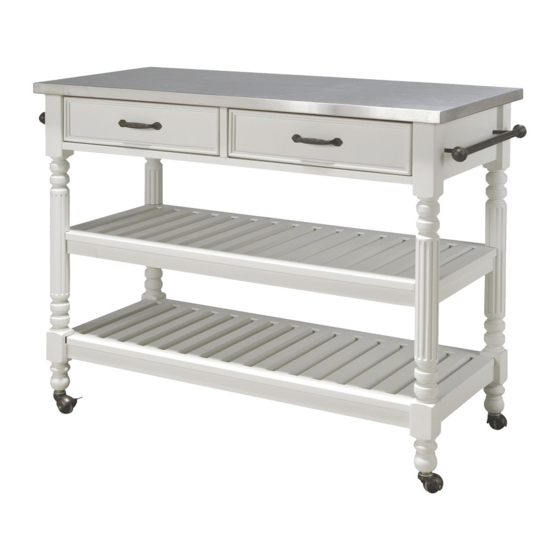
Savannah Kitchen Cart
IMPORTANT NOTE
Carefully remove all the parts from the carton and put
them individually on a soft cloth to prevent scratches
or other damages occuring to the parts.
We have taken great care in the design of this
product and request that you carefully and strictly
follow our assembly instructions to ensure a
completed product as it was designed.
Part List
A.
Top
1 Pc.
B.
Side Frame
1 Pc.
Hardware List
Hex Wrench
1 Pc.
Small Hex Wrench
1 Pc.
Tools required for assembly : Phillips screwdriver
C.
Side Frame
1 Pc.
Cam Lock
Cam Lock Screw
13 Pcs. (+1 extra)
13 Pcs. (+1 extra)
Caster
2 Locking
Head Cap Bolt (short)
2 Non-Locking
5 Pcs.(+1 extra)
4 Pcs.
Home Styles Consumer Assistance: www.homestyles-furniture.com,
servicedesk@homestyles-furniture.com, 888-680-7460, 877-831-0319
E.
Front Rail
1 Pc.
F.
Back Rail
1 Pc.
G.
Shelf
instructions for steps to complete drawer assembly)
2 Pcs.
Wood Screw (short)
Wood Screw (long)
for bottom drawer
for side drawer
12 Pcs. (+1 extra)
16 Pcs. (+1 extra)
Head Cap Bolt (long)
8 Pcs. (+1 extra)
(Knock-Down Construction,
please refer to the last page of
Machine Screw
4 Pcs.
Flat Washer
Spring Washer
8 Pcs. (+1 extra)
8 Pcs. (+1 extra)
D.
Divider
1 Pc.
H.
Drawer
2 Pcs.
Pull Handle
2 Pcs.
Side Bar
2 Pcs.
Advertisement
Table of Contents

Related Manuals for Home Styles Savannah Kitchen Cart

Summary of Contents for Home Styles Savannah Kitchen Cart
- Page 1 Side Bar 2 Non-Locking 1 Pc. 5 Pcs.(+1 extra) 8 Pcs. (+1 extra) 8 Pcs. (+1 extra) 8 Pcs. (+1 extra) 2 Pcs. 4 Pcs. Tools required for assembly : Phillips screwdriver Home Styles Consumer Assistance: www.homestyles-furniture.com, servicedesk@homestyles-furniture.com, 888-680-7460, 877-831-0319...
- Page 2 Assembly Instructions 2 IMPORTANT * Please keep Hex Wrench in a safe place as you may need to tighten up the Head Cap Bolts in the future. * Do not tighten up all the screws until each part is properly assembled. * Use a soft cloth between these parts and the fl...
- Page 3 Assembly Instructions 3 Head Cap Bolt (short) Cam Lock Cam Lock Screw STEP 3 Assemble Front Rail (E), Divider (D) and Back Rail (F) with Cam Lock and Head Cap Bolt (short). Attach unit to Side Frame (B) with Cam Locks. (See fi...
- Page 4 Assembly Instructions 4 Cam Lock Head Cap Bolt (long) Spring Washer Flat Washer Flat Washer STEP 5 Spring Washer Head Cap Bolt Attach Side Frame (C) to unit with Cam Locks, Head Cap Bolts (long), (long) Spring Washers and Flat Washers. Locking Caster Non-Locking Caster...
- Page 5 Assembly Instructions 5 Side Bar Head Cap Bolt (short) Figure 3 STEP 7 Turn the unit to its’ upright position. Attach Side Bars to unit with Head Cap Bolts (short). (See fi gure 3) STEP 8 Place Top (A) onto unit with Cam Locks.
- Page 6 Assembly Instructions 6 Drawer (H) STEP 1 Attach H1 to H3 and H4, using a Phillips screwdriver and long wood screws (4X), tighten halfway. Figure 1 Attach H2 to H3 and H4 using long wood screws (4X), STEP 2 tighten halfway. (See fi gure 1) Slide H5 into the grooves in H3 and H4.
Need help?
Do you have a question about the Savannah Kitchen Cart and is the answer not in the manual?
Questions and answers