Table of Contents
Advertisement
Quick Links
Accessories
MX-MT-v26-V/
MX-MT-v26-V-XL
Mx-M-OWA-AU/
Vandalism Set/
Mx-M-OWA-AU-b
Vandalism Set for On-Wall
On-Wall Set with Audio
Set with Audio
*Variant Mx-v26B supports MOBOTIX MxBus modules
Delivered Parts
1.12
1.1
1.11
1.10
1.9
1.8
1.7
Delivered Parts Vandalism Set/Vandalism Set for On-Wall Set with Audio
Except for the vandalism ring, the delivery of both sets is identical (items 2.1 and 2.1a).
2.1
Connecting the v26
Lens
Key
LEDs
Installing the Lens
1. Remove the dome
Unscrew the dome by turning it counter-
clockwise).
2. Install the lens
Using the red lens wrench, screw the lens into
the lens mount.
After initial operation of the camera, remem-
ber to adjust the focus of the lens (see «Initial Operation» on page 2).
Inserting /Exchanging the SD Card
All camera models can use the integrated microSD card (SDXC) to record video data. In order to exchange the microSD card, please proceed as outlined
in the following instruction. For information on reliable SD cards, please see the MOBOTIX website www.mobotix.com > Support > Download Center >
Documentation > White Lists in the document microSD Card Whitelist for MOBOTIX Cameras.
When replacing the SD card, make sure that recording has been deactivated in the browser (Admin Menu > Storage > Storage on External File Server /
Flash Device; activate recording again in the same dialog). To get to the back of the main board, you may have to loosen the screws at the left and right
side of the main board support, and tilt the main board support slightly forward (see «Installing the v26», Step 7).
1. Remove the SD card
If a microSD card has been installed, gently
press with your finger as indicated by the arrow
until you hear a click. Then release the SD
card. The card is protruding slightly and can
be easily removed.
Installing the Mx-A-IOA-IC
For the Mx-v26A/B, you can use the optionally available Mx-A-IOA-IC to attach external sensors using the signal inputs and
to switch other devices via the signal outputs. When used with the the Mx-v26B, you can also attach MxBus devices (e.g., an
MX-GPS-Box). To attach the Mx-A-IOA-IC Module, you need to remove the dome, You may also have to loosen the screws at the
left and right side of the main board support, and tilt the main board slightly forward (see «Installing the v26» step 7).
1. Attach the connection cables
Attach the connection cables as shown in the terminal connector overview.
Terminal Connectors
MxBus connectors
Output 1 A
Output 1 B/GND
Output 1 12 V
Output 2 A
Output 2 B/GND
Output 2 12 V
Input 1 –
Input 1 +
Input 2 –
Input 2 +
Installing the v26
Use the drilling template on the back for this step. Mark the holes for dowels or screws If required, drill the holes for the dowels, push them in and attach
the v26 with dowels and screws.
1. Connect the cables
Guide the cables (network cable, USB
cable, MxBus wires and signal input/
output wires) through the cut-out in the
sealing. When doing this, make sure that
you do not damage the cables/wires.
Connect the cables/wires to the v26.
2. Mount the reflection protection
To avoid reflections within the interior
of the white housing, you should apply
the supplied reflection protection (two
pieces, item 1.12). In the black housing,
the protection also covers the silver-col-
ored screws. Place the ring around the
main board support. Press the ring into
the recess of the housing. Turn the housing on its back.
Now take the disc and pull it gently
apart at the cut. Place the disc around
the cables where the sealing and the
housing meet. Push the disc down on
the opening in the housing.
3. Place sealing on v26
Place the sealing on the back of the
v26 as shown.
4. Install the v26
Press the camera and the wall sealing
against the ceiling and align the holes
with the holes for the dowels/screws.
You may have to loosen the fastening
Mx-A-IOA-IC
for MxBus modules* and
signal inputs/outputs
1.2
1.3
1.4
1.5
1.6
2.2
2.3
2.4
2.1 a
MxBus functionality is only supported
by the camera variant Mx-v26B.
–
Relay
pot.-
free
Output 1
12 V
–
Outputs
–
Relay
pot.-
free
Output 2
12 V
–
Inputs
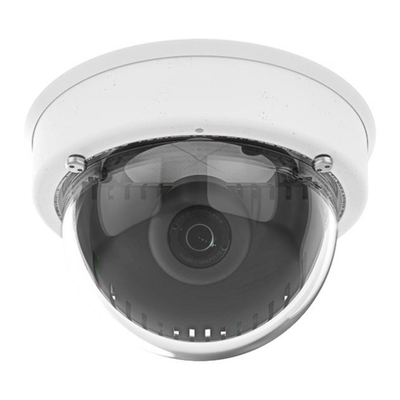
v26 Indoor Dome
Quick Installation
Item
Count
Part Name
1.1
1
v26 with standard dome
1.2
1
Sealing
1.3
1
Ethernet patch cable, 50 cm/19.7 in, black
1.4
1
Allen wrench 2.5 mm
1.5
1
Torx wrench TX20
1.6
1
microSD card pre-installed (SDHC montiert, SDXC supported)
1.7
1
Lens wrench, red
Allen screws M4x16 mm, black (for black housing)
1.8
4
Allen screws M4x16 mm, silver-colored (for white housing)
1.9
4
Stainless steel washers Ø 5.3 mm
1.10
4
Dowels 8 mm
1.11
4
Stainless steel wood screws with Torx head 4.5x60 mm
1.12
1
Reflection protection
Item
Count
Part Name
2.1
1
Vandalism ring
Vandalism ring
2.1a
1
(Vandalism set for On-Wall set with audio)
2.2
1
Vandalism dome, reinforced
2.3
4
Security screws
2.4
1
Screwdriver bit for security screws
You can find detailed information on the installation and connections of
the v26 in the Camera Manual Q26 (PDF, available on www.mobotix.com >
Support > Download Center > Documentation > Manuals).
Regarding the initial operation of the v26, please see the D25 Camera
Manual in Chapter 3, «Initial Operation».
Use a suitable device for operating the camera key (e.g., a screw driver).
Note on Using the v26 With Lens B237
When using the v26 with the lens B237, you must tilt the lens by at least
5 degrees downward! If this angle is lower than 5 degrees, you will expe-
rience image distortions induced by the curvature of the dome!
2. Insert the SD card
Insert the microSD card and gently press with
your finger as indicated by the arrow until you
hear another click.
Make sure that the SD card is fully inserted.
2. Insert the Mx-A-IOA-IC
Hold the Mx-A-IOA-IC over the receptacle on
the main board (red arrow in figure). Make
sure that the green terminal connector block
is pointing upward (towards the SD card, see
red arrow in figure).
Use one finger to carefully press the board of
the module onto the receptacle. Make sure that
the Mx-A-IOA-IC is fully inserted.
screws (see below) and rotate the main board support to get to these
screws. Insert the screws with washers and tighten them.
5. Adjust viewing direction
Release the fastening screws and rotate the
camera into the desired viewing direction.
Tighten the screws (torque 0,4 Nm) again
once you are finished.
6. Start the camera and focus the lens
For the first start of the camera and for adjusting the focus of the lens, see
«Initial Operation» on page 2.
7. Set the tilt angle of the lens
Make sure that the lens is tilted properly.
If this is not the case, loosen the screws
to the right and left of the mainboard
support and tilt the camera. Tighten
the screws again once you are finished.
8. Install the dome
Mount the dome. If you are using the vandalism
set, install the reinforced vandalism dome instead.
9. Close the screw holes
If you do not use the vandalism set, you should
close off the four holes using the supplied black
or silver screws, depending on the color of
the set.
v26 + B237
>= 5 °
Advertisement
Table of Contents

Related Manuals for Mobotix v26


Summary of Contents for Mobotix v26
- Page 1 MX-GPS-Box). To attach the Mx-A-IOA-IC Module, you need to remove the dome, You may also have to loosen the screws at the left and right side of the main board support, and tilt the main board slightly forward (see «Installing the v26» step 7).
- Page 2 MOBOTIX, the MX logo, MxPEG and MxActivitySensor are trademarks of MOBOTIX AG registered in the Euro- pean Union, the U.S.A., and other countries • Information subject to change without notice • MOBOTIX does not assume any liability for technical or editorial errors or omissions contained herein • All rights reserved •...
Need help?
Do you have a question about the v26 and is the answer not in the manual?
Questions and answers