
Subscribe to Our Youtube Channel
Related Manuals for Zip IP-CAM360


Summary of Contents for Zip IP-CAM360
- Page 1 IP-CAM360 FISHEYE INDOOR IP CAMERA 4K XIPCAM360 Version: IPC006 Email: support@zipnvr.com Last Revised 13/05/2019...
-
Page 2: Table Of Contents
TABLE OF CONTENTS Page Contents Special Note IP-CAM360 Fish Eye Camera General Information IP-CAM360 Main Features Mounting the IP-CAM360 Powering the IP-CAM360 IP-CAM360 Cable connections Audio In / Out IR LEDs Overview Range of IP Address Product Description Operation Environment... -
Page 3: Special Note
Date/Time Information 5.3.6.2 Users 5.3.6.3 Info 5.3.7 Tools 5.3.7.1 Firmware Update 5.3.7.2 Load Default 5.3.7.3 Reboot Local Setting 5.4.1 Record Path 5.4.2 Download Path 5.4.3 Snapshot (Capture) Path 5.4.4 File Type 5.4.5 Interval 5.4.6 Capture Type Technical Specifications for IP-CAM360... -
Page 4: Ip-Cam360 Fisheye Camera
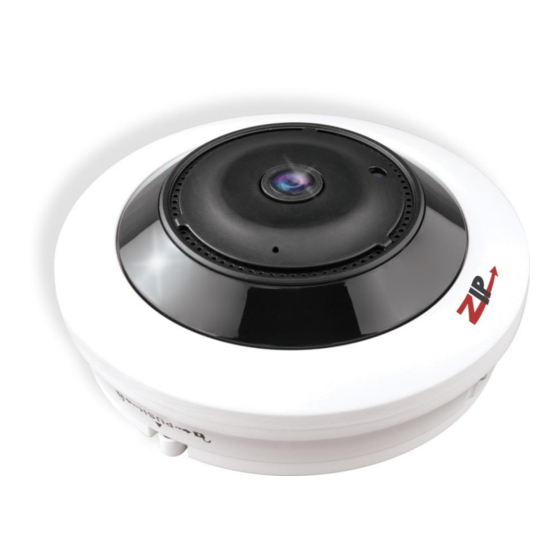
1. IP-CAM360 Fisheye Camera General Information A Fisheye camera is designed for shooting very wide angles, usually 180 degrees. A fisheye lens, also known as an "ultra wide" or "super wide" lens, is a type of wide angle lens which can capture an extremely wide image, typically around 180 degrees. -
Page 5: Mounting The Ip-Cam360
1.3 Mounting the IP-CAM360 The Fisheye camera can provide various display modes and these differ according to where the camera is mounted. The display modes can also be displayed as a single view or a multiple view via the software in the camera. Recordings set in the web browser interface can be recorded on the internal SD card and in playback mode you have the facility to take a video clip or frame capture to your P.C. -
Page 6: Powering The Ip-Cam360
Powering the IP-CAM360 The IP-CAM360 can be powered using a 12vDC power supply or via PoE. The camera draws approximately 600mA using a 12vDC regulated power supply when IRs are switched on, so to enable for headroom when first powered up, it is recommended using a minimum of a 12vDC 750mA regulated power supply. -
Page 7: Overview
2.1 Range of IP Address The ZIP range of IP cameras use an identical menu system which is detailed below. The default IP address is 192.168.10.1. If you are connecting this camera to a network which is not on a 192.168.10 address, then you will have change the IP address in the camera. -
Page 8: Ip Camera Connection
3. IP Camera Connection 3.1 Connection direct to PC via a crossover cable Connect IP camera to a PC via a crossover cable, with power input connected to a DC 12V power supply and set the IP addresses of the PC and IP camera in the same network subnet. The IP camera will communicate with the PC if the IP address in the camera is changed so that it is in the same subnet as the PC. -
Page 9: Device Operation Instructions
4. Device Operation Instructions 4.1 Check Connection 1. The default factory IP address for the IP camera is 192.168.10.1 and the subnet mask is 255.255.255.0. Change your computer IP address to the same network subnet as the IP camera, for example: IP Address of PC to 192.168.10.100 and subnet mask 255.255.255.0 same as that of the IP camera. - Page 10 Step B Click on Properties Step C Click on Internet Protocol Version 4 (TCP/IPV4) and click Properties Step D Click on Advanced Step E Click Add Step F Add an IP address in the range of the IP cameras but not the IP camera/s itself then click OK This will allow ZipFinder to access not only the 192.168.0.? addresses but also the 192.168.10.
- Page 11 2. Run ZipFinder by double clicking icon. It will search and display any online IP address and its IP address, port number, number of channels, device type and version, subnet mask, gateway, MAC address and connection pattern. 3. You will see that the IP camera address 192.168.10.1 displays. To change the address, click on the box to the left of the IP address.
-
Page 12: Installation Of Controls And Login To System
4. You can now change the IP address by completing the section at the bottom of the screen and click on Modify.See note below. Note you need to enter the IP camera password that is 777777, the new IP address, Media Port 8240, Web Port 80, Gateway (Local IP of Router) &... -
Page 13: Browser Menu
5. Web Browser Menu 5.1 Live Display Open IE and enter the IP address of the camera e.g (http://192.168.10.1) to open a login box as shown below: In the login box enter your user name (admin by default) and password (777777) and then press Login to open a preview frame, example as shown below:... -
Page 14: Live Screen Display
5.1.1 Live Screen Display Control Buttons in the preview frame are described below: 1. Live Live Preview Mode 2. Playback Playback recorded video 3. Remote Setting Menus for camera setup, recording, networking, Email etc.. 4. Local Setting Setting paths for PC for video streaming and capture. Information - User, Web and Plugin information Logout... - Page 15 Color Colour setting button, for setting of hue, brightness, contrast, saturation and sharpness of the picture. 12. Display Mode Display Mode On / Off Ceiling Mount The above display modes can be viewed when the camera is mounted on the ceiling. The following shows the Display Modes for Wall, Desktop and Tilt modes.
-
Page 16: List Of Display Modes For Different Mount Types
5.1.2 List of Display Modes for the different Mount Types Type Views View Variations VR / Cylinder / 2PTZ / 4PTZ / Panorama 180 / Ceiling Panorama 360 / Panorama 360 + 1PTZ / Panorama 360 + 3PTZ / Panaroma 360 + 6PTZ / Panarama 360 + 8PTZ / FishEye + 3PTZ / FishEye + 8PTZ VR / Panorama / 4PTZ / Panorama +3PTZ /... -
Page 17: Playback
Playback Playback reads the recorded files from the internal SD card (if fitted or optional) and then plays backfrom the browser. 5.2.1 Playback buttons The calendar should display todays date with day in red box and current year and month <... - Page 18 6. Screen Display settings Normal Proportions Full Screen Bespread – Wide View Proportions The magnifier + when clicked increases record timeline to provide more accurate time selection whereas the magnifier – decreases and reduces timeline. 8. Timeline Moving the mouse on the timeline displays the time selected in yellow. Recordings (These are displayed in green (continuous recording) yellow (motion) or red (alarm) as defined in the Remote Settings menu >...
-
Page 19: Remote Setting
5.3 Remote Setting 5.3.1 Camera 5.3.1.1 OSD Menu Name: Name of the IP camera Flicker Control: 50Hz (UK) / 60Hz (USA) Transparency: Choose transparency of camera name and time in preview mode (smaller value indicates higher transparency) (default = 64) Show Name: Text in red colour: You can locate the position of the camera name for the channel by dragging the information in red to another position in the preview picture and saving it. -
Page 20: Camera Settings
5.3.1.2 Camera Settings Click on Camera Settings to open the following page: IR-Cut Mode: Auto / Colour / Black and White IR-Cut Delay: IR-cut switching delay 1 ~ 36 seconds (default = 2) Flip: Flip picture Mirror: Reverse picture view Corridor Mode: Angle rotation: (0°... -
Page 21: Privacy Mask
5.3.1.3 Privacy Mask Click on Privacy Mask in Camera Menu to open the following page: This option allows you to mask up to 4 areas at a time. Procedure of setting Video Masking: (default = off) 1. Tick the box marked Privacy Mask 2. -
Page 22: Roi (Region Of Interest)
5.3.1.4 ROI (Region of Interest) Click on ROI in Camera Menu to open the following page: What is ROI (Region of Interest) Region of Interest is where you want to select from 1 to 8 areas in a picture with improved frame rate and quality, so allowing non-ROI areas to preview in lower frame rate and quality settings. -
Page 23: Record
5.3.2 Record 5.3.2.1 Record Settings Click Record Settings in Record Menu This function controls recording, pre-recording and the recording type (main stream or substream) on an SDHC card facility incorporated in the camera. The card must be Class 10 or above. SDHC cards are not included in the cameras. -
Page 24: Normal Schedule
5.3.2.2 Normal Schedule The schedule for setting up record information covers one week from Sunday through to Saturday, with each box representing a 30 minute recording time. For each day there are three lines covering 24x7 normal recording in green colour, motion recording in yellow colour and red in alarm mode recording. -
Page 25: Network
5.3.3 Network Click on Network Parameters in Network to open the following page: 5.3.3.1 Network Type: DHCP (Automatically Acquired), PPPOE, Static (Manually Configured – Default) Client Port: Media (management) port Default = 8240 HTTP Port: Web port Default = 80 IP Address: IP address (Default = 192.168.10.1) Subnet Mask: Subnet Mask (Default = 255.255.255.0) Gateway: Default gateway of the device ( Default = 192.168.10.254) -
Page 26: Encoding
5.3.3.2 Encoding Click on Encoding in Network Menu to open the following page: Main Stream Sub Stream Mobile Stream MobileStream Stream MainStream/Substream/MobileStream Options: Tick Main Stream / Sub Stream / Mobile Stream Note: MobileStream can be disabled You can set resolution, frame rate, video encoding, encoding level, audio, I frame interval, variable frame rate and bit stream size respectively for main stream, sub-stream and mobile stream... - Page 27 Video Code Type: H264 / H265 (Default H265) Must reflect the IP camera setting. H265 is an algorithm for compression of data that is classed as High Efficient Video Coding (HEVC) that gives you lower processing overheads and thus uses less disk hard drive storage space. Savings of up to 50% hard drive storage space can be made.
-
Page 28: Email Settings
5.3.3.3 E-Mail Settings If the IP camera has Email options, then this can be used, but it is only applicable to this camera channel. The NVR or DVR used, may have a global Email facility that avoids replication for each channel, so this option may not be the best option to use. -
Page 29: Ddns
5.3.3.4 DDNS This option allows the camera to use a third party DDNS service to determine the current IP address. These services are DYNDNS or NO_IP 6.4 DDNS Configuration Click on DDNS Configuration in Network Parameter menu to open the following page: ation: Dynamic DNS configuration - used with server for access from an extranet. - Page 30 5.3.3.5 IP Filter Select IP Filter to allow, restrict or block IP connections. Filter mode: Three modes are available - Allow all IP connections, Allow the selected IP connections, Block the selected IP connections. Add: Add any allowed or blocked IP addresses Delete: Delete any IP address no longer required...
- Page 31 5.3.3.6 RTSP Port Select RTSP Port to open the Realtime Streaming Port. This port must be open to view video streaming. RTSP Enable or disable RTSP. RTSP is enabled by default. RTSP Port: The RTSP port is 1240 by default. The NVR/DVR RTSP port is 1240 by default. On a remote connection these ports must be unique on the same network.
- Page 32 5.3.3.7 FTP Settings Click on FTP menu to open the following page. You will need an FTP server to use this. The FTP service setting is used with the alarm function to upload images or videos to an FTP server. Note: If FTP is switched on then the Email service will not run.
- Page 33 5.3.4 Alarm 5.3.4.1 Motion Detection Click on Motion in Motion Detection menu. Enable: Click in box to enable motion detection. Sensitivity: Set the motion detection sensitivity level ( 1~ 8) The higher the level the less pixel colour changes needed to record Alarm Out: Click in box to enable alarm output.
- Page 34 Procedure for setting Motion Detection 1. Check Enable Motion Detection. 2. Press down and hold the left mouse button and drag mouse over area for motion detection. 3. Set the sensitivity for mobile detection (1 ~ 8 and the larger the value the higher the sensitivity). 4.
- Page 35 5.3.4.2 Alarm Settings Click on Alarm Settings in Alarm menu: Alarm Input: Select OFF, NO (Normally Open) or NC (Normally Closed) Latch Time: Alarm latch recording time (5, 10, 20, 30 seconds) Send Email Click on Send Email box to send email ...
- Page 36 5.3.4.3 Lens Covered Click on Lens Covered in Alarm Parameter menu. Enable: Tick Enable (checked by default) to activate Sensitivity Level and Email Link options. Sensitivity: Set security level for lens blocking (1~8). The higher value the higher the security level. Send Email Disabled by default.
- Page 37 5.3.5 Device This menu includes optional functions i.e SD Card, Audio Setting and Log information. Note that if SD card is not fitted there will be no SD card format option. 5.3.5.1 SD Card(optional function – option available if menu is displayed) (If the camera menu displays SD card function this does not imply that an SD card is fitted.
- Page 38 5.3.5.2 Audio Click on Audio in Device menu. Click the Enable Audio box to expand menu options. Procedure for setting Audio Enable Audio: Check that Enable Audio has been ticked (default = not enabled) Output Volume: Set Output Volume (ranging 0~10). Input Volume: Set Input Volume (ranging 0~10).
- Page 39 5.3.5.3 Log Click on Log, in Device menu. Major Type: There are eight types of logging information held and include - System Log, Config Log, Alarm Log, User Log, Record Log, Storage Log, Network Log and All Log. Each page of the log can display up to 10 records and up to 100 pages can be held at anyone time. Therefore a total of 1000 log records can be held.
- Page 40 5.3.6 System System parameters include Date and Time Information, User Setup Information, Camera System Information and Smart Analysis Reports. 5.3.6.1 Date/Time Information Click on Date/Time in System Parameters menu. The device time, system time, date format and time format contained in the Date and Time information can be manually set and saved.
- Page 41 NTP: Check Enable NTP option, input the address of time server and choose a time zone and then save the setting. The system will correct time in accordance with the time server. There are three time servers that you can select from. Synchronise with Computer Time: Check Synchronize With Computer Time option and the camera will use the PC as a time server to correct the date and time.
- Page 42 5.3.6.2 Users Click on Users in System Parameters menu. This allows you to set user access authority and login user and password settings. By default there is only one administrator (admin) and has full permissions and controls up to six users. The six users can be restricted from making parameter settings, live viewing and reviewing playback.
- Page 43 5.3.6.3 Info Click on Info in System menu. This menu describes the system information held on the camera including the device name, serial number, Hardware Version, Software Version, I.E Client version, MAC address and P2PID. You can use the P2P ID code for mobile phone parameter setup. Note that the device name, serial number and P2P ID code have been removed...
- Page 44 This menu includes Firmware Update, Load Default and Reboot options. 5.3.7.1 Firmware Update Click on Firmware Update in Tools menu. Scan: Click on scan button to locate Zip folder storing firmware version. Update will be unavailable if the update files do not match the target device. 5.3.7.2 Load Default Click on Load Default in Tools menu.
- Page 45 5.3.7.3 Reboot Click on Reboot in Tools menu Click on Auto Reboot down arrow key and select Enable, then click Reboot. This option allows you to select an auto reboot on a scheduled basis. The default is not activated. Auto Reboot (default = not activated) Once set you can schedule an auto reboot Every Week / Everyday / Every Month.
- Page 46 5.4 Local Setting Local Setting Options For taking manual recordings, downloads and video captures to your PC hard drive when in live mode, you need to create the respective folders on your PC first. You can use the default folder names shown below or amend them to new path names.
- Page 47 Technical Specifications for IP-CAM360 Model IP-CAM360 Protocol Version ONVIF 2.6 1/1.7” CMOS Image Sensor Motion Detection 4K (8Mpx) 4 Zones Resolution Privacy Masking 0 Lux IRs on Min. Ilumination Camera OSD Menu Input Voltage PoE or 12vDC Audio Microphone Built–in microphone Power Consumption <7w 600mA...
Need help?
Do you have a question about the IP-CAM360 and is the answer not in the manual?
Questions and answers