Advertisement
Quick Links
Advertisement

Related Manuals for Ceyear 4024 Series


Summary of Contents for Ceyear 4024 Series
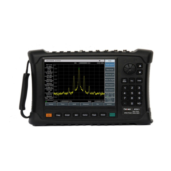
- Page 1 Spectrum Analyzer 4024D/E/F/G 9 kHz ~ 20 GHz / 26.5 GHz / 32 GHz / 44 GHz Maintenance Manual...
-
Page 3: Product Overview
Product Overview 1.1 Features The 4024 series spectrum analyzer embraces such advantages as wide working frequency band, high performance indexes, high sweep speed, multiple test functions and easy operation. The integration of 8.4 inch LCD and capacitive touch screen improves the display definition and operation convenience. -
Page 4: Working Principle
Working principle The 4024 series spectrum analyzer consists of 4 mutually independent function modules with standard interfaces, namely microwave/millimeter-wave frequency conversion module, frequency synthesis module, IF signal processing module, and data processing, display and control module. Such a design facilitates maintenance of the main unit and replacement of the parts, and also significantly reduces the re-debugging workload of the main unit after the module replacement. - Page 5 The frequency synthesis module is mainly used to provide the required LO signals to the three mixers in the microwave/millimeter-wave frequency conversion module and the fourth mixer in the IF signal processing module. It consists of seven phase-lock loops of 5.3 GHz ~ 5.55 GHz first LO, 6 GHz ~ 12 GHz second LO, 3,200 MHz third LO and 109 MHz fourth LO, which will directly determine the phase noise, sweep speed, sideband stray, etc.
- Page 6 Analysis on common faults 3.1 Lighting failure of power indicator lamp Fault cause: The keyboard has fault or the CPU board has communication fault Instrument to be repaired: Digital display megawatt multimeter FLUKE 1508 Repair method: Check whether the DC voltage output by the adapter is 14 V ~ 16 V; If the adapter is normal, firstly replace the front cover assembly;...
- Page 7 Fault cause: The microwave/millimeter-wave frequency conversion module has output fault. Instrument to be repaired: Synthetic signal generator 1465H Repair method: Eliminate the cable connection fault. Replace the microwave/millimeter-wave frequency conversion module. 3.7 SWR deviation at input port Fault cause: The RF front end connection has fault or the connection cable has fault Repair method: Check if the connection cables between the RF input connector, blocking module and programmable step attenuator are reliable or loose.
- Page 8 Repair of parts When the 4024 series spectrum analyzer has any fault and the casing shall be opened to check the fault cause or the spare parts and complete parts shall be replaced, please refer to the schematic diagram of...
- Page 9 Remove the battery cover assembly (17), and then remove the battery (11). Fig. 2 Removal of Battery Gently place the 4024 series spectrum analyzer on the table with back upwards, and remove eight fixing screws (four on the back and four on the side) of the casing with a Phillips screwdriver.
- Page 10 Fig. 4 Connection Cables between the Front and Rear casings Remove the rear casing assembly: Firstly, remove and replace the frequency synthesis board (12): Firstly, remove 6 fixing screws of the frequency synthesis board (12) in the rear cover assembly (19);...
- Page 11 a. Remove 6 fixing screws b. Loosen 3 semi-rigid cable connectors c. Remove 50-core cables Fig. 5 Removal of the Frequency Synthesis Board The microwave frequency conversion module (13) after removal of the frequency synthesis board (12) is as shown in the following figure. The removal and installation processes are as follows: Remove 4 fixing screws between the microwave frequency conversion module (13) and the rear cover assembly (19).
- Page 12 Remove the front casing assembly: Firstly, remove and replace the IF channel plate (7): Remove 4 fixing screws of the IF channel plate (7), Remove the interconnecting 50-core flat cables between the CPU board (9) and the IF channel plate (7), The installation process is reverse to the removal process.
- Page 13 Frequency range: 250 kHz ~ 50 Power output: -100 dBm ~ +15 1465H (with 90 Synthesized Frequency accuracy: ±0.02% signal programmable Ceyear The power level can be calibrated generator step attenuator and stored option) It has internal and external AM...
- Page 14 cable with the PC through the GPIB card, and connect 4024 to be tested with the PC through the direct-connected network cable. It is as shown in the figure: GPIB card GPIB cable Signal source Adapter 2.4 mm cable Power meter Power Adapter sensor...
- Page 15 Fig. 11 Set Address Interface Attention: In case of the initial compensation, the following steps c) and d) shall be carried out. If steps c) and d) have been carried out and “PowerMeter.powdoc” and “cal.txt” files have been generated under the current directory, start from step 2 directly in case of re-compensation of other spectrometers.
- Page 16 Check 4024 series spectrum analyzer to ensure that there are no IF DAC files and compensation files. If a DAC or compensation file exists, it shall be deleted firstly. The specific operation is as follows: Connect the PC with the 4024 spectrum analyzer with a point-to-point network cable, open the 4024 host folder: “ftp://172.141.xx.xx/”...
- Page 17 Frequency range: 250 kHz ~ 50 Power output: -100 dBm ~ +15 dBm 1465H (with 90 dB Frequency accuracy: ±0.02% Synthesized signal programmable step Ceyear The power level can be calibrated generator attenuator option) and stored It has internal and external AM...
- Page 18 Test steps Connect the computer with the spectrum analyzer with a point-to-point network cable; connect the BNC cable with 10 M reference input of the spectrometer and 10 M reference output of the signal source, and then connect the 2.4 mm (m-m) low loss RF cable with the 1465H signal generator, and finally connect the spectrometer RF input with the 2.4mm (m-m) low loss RF cable with 2.4 mm (f-f) adapter.
- Page 19 through 【System】-[Network Configuration]. Attention: The IP address of the 4024 spectrometer and PC shall be located on the same network segment. If they are different, the IP of the computer or spectrometer shall be set to make it within the same network segment (for example, if the IP of the spectrometer is 172.141.11.202, the IP of the computer shall be set to 172.141.11.xx).
Need help?
Do you have a question about the 4024 Series and is the answer not in the manual?
Questions and answers