Sign In
Upload
Download
Table of Contents
Contents
Add to my manuals
Delete from my manuals
Share
URL of this page:
HTML Link:
Bookmark this page
Add
Manual will be automatically added to "My Manuals"
Print this page
×
Bookmark added
×
Added to my manuals
Manuals
Brands
Ceyear Manuals
Measuring Instruments
3672 Series
Quick start manual
Ceyear 3672 Series Quick Start Manual
Vector network analyzer
Hide thumbs
1
2
3
4
Table Of Contents
5
6
7
8
9
10
11
12
13
14
15
16
17
18
19
20
21
22
23
24
25
26
27
28
29
30
31
32
33
34
35
36
37
38
39
40
41
page
of
41
Go
/
41
Contents
Table of Contents
Bookmarks
Table of Contents
Table of Contents
1 About this Manual
Related Documents
2 Preparation before Use
Preparation before Operation
Unpacking
Setup and Installation of the Instrument
Power On/Off
Correct Use of Connectors
Operating System Configuration
System Recovery
Program Installation
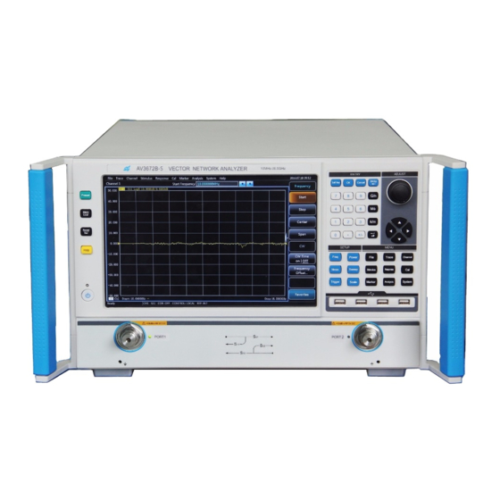
Instrument Appearance
Description of Front Panel
Description of Rear Panel
Mouse Interface
3 Typical Applications
Analyzer Preset
Measurement Parameters Selection
S Parameter
Change Measurement Types of the Trace
Frequency Range Setup
Signal Power Level Setup
Sweep Setup
Sweep Type
Sweep Time
Data Format and Scale Setup
Data Format
Scale
Data Output
Save and Recall Files
Measurement Result Printing and Displaying
4 Getting Help
Advertisement
Quick Links
Download this manual
3672 Series
Vector Network Analyzer
Quick Start Guide
Table of
Contents
Previous
Page
Next
Page
1
2
3
4
5
Advertisement
Table of Contents
Need help?
Do you have a question about the 3672 Series and is the answer not in the manual?
Ask a question
Questions and answers
Related Manuals for Ceyear 3672 Series
Measuring Instruments Ceyear 3680A Quick Start Manual
Cable & antenna analyzer (32 pages)
Measuring Instruments Ceyear 3986 Series User Manual
Noise figure analyzer (241 pages)
Measuring Instruments Ceyear 3986 Series Programming Manual
Noise figure analyzer (139 pages)
Measuring Instruments Ceyear 3656 Series Quick Start Manual
Vector network analyzer (53 pages)
Measuring Instruments Ceyear 3656B Quick Start Manual
Vector network analyzer (53 pages)
Measuring Instruments Ceyear 3672C Quick Start Manual
Vector network analyzer (41 pages)
Measuring Instruments Ceyear 3672D Quick Start Manual
Vector network analyzer (41 pages)
Measuring Instruments Ceyear 3672E Quick Start Manual
Vector network analyzer (41 pages)
Measuring Instruments Ceyear 4957D Quick Start Manual
Microwave analyzer (36 pages)
Measuring Instruments Ceyear 2498C User Manual
Optical power meter (15 pages)
Measuring Instruments Ceyear 4024 Series Quick Start Manual
Spectrum analyzer (40 pages)
Measuring Instruments Ceyear 4024 Series Maintenance Manual
Spectrum analyzer (19 pages)
Measuring Instruments Ceyear 4051 Series User Manual
Signal/spectrum analyzer (751 pages)
Measuring Instruments Ceyear 2438 Programming Manual
Microwave power meter (212 pages)
Measuring Instruments Ceyear 4024 Series User Manual
Spectrum analyzer (218 pages)
Measuring Instruments Ceyear 87234 Series User Manual
Usb peak/avg power meter (89 pages)
This manual is also suitable for:
3672a
3672c
3672d
3672e
3672a-s
3672b-s
...
Show all
3672c-s
Table of Contents
Print
Rename the bookmark
Delete bookmark?
Delete from my manuals?
Login
Sign In
OR
Sign in with Facebook
Sign in with Google
Upload manual
Upload from disk
Upload from URL


Need help?
Do you have a question about the 3672 Series and is the answer not in the manual?
Questions and answers