Table of Contents
Advertisement
Quick Links
Advertisement
Table of Contents

Related Manuals for Vents ICF Series


Summary of Contents for Vents ICF Series
- Page 1 USER’S MANUAL Impulse centrifugal fan...
-
Page 2: Table Of Contents
CONTENTS Safety requirements ..................................3 Purpose ........................................ 5 Delivery set ......................................5 Designation key ....................................6 Technical data ....................................6 Design and functioning ................................8 Mounting and set-up .................................. 8 Connection to power mains ..............................9 Commissioning ....................................12 Technical maintenance ................................13 Storage and transportation regulations .......................... -
Page 3: Safety Requirements
SAFETY REQUIREMENTS • Please read the user’s manual carefully prior to installing and operating the unit. • All user’s manual requirements as well as the provisions of all the applicable local and national construction, electrical, and technical norms and standards must be observed when installing and operating the unit. - Page 4 • Do not touch the unit controls • Do not wash the unit with with wet hands. water. • Do not carry out the • Protect the electric parts of the installation and maintenance unit against ingress of water. operations with wet hands. •...
-
Page 5: Purpose
PURPOSE The ICF series impulse centrifugal fan is applied in ventilation and smoke extraction systems of underground parkings and garages. The fans with fire resistance ratings +200 °C, +300 °C and +400 °C are designed for 2 hours of non-stop operation for smoke extraction. -
Page 6: Designation Key
DESIGNATION KEY I C F - X - X - X Fan type Impulse centrifugal fan Thrust: 100N Number of poles: 4 (single-speed) 4/6 (double-speed) 4/8 (double-speed) Fire resistance: _ – up to 55 °C 200/2 – up to 200 °C/2 hours 300/2 –... - Page 7 Thrust Max. operating Power supply Frequency Air flow Input Fire Model (impulse) velocity temperature voltage [V] [Hz] [m3/h] power [kW] [min-1] resistance [m/s] [°C]* 50N, single-speed ICF–50N–4–… –25 – +55 °C 55 °C ICF–50N–4–…–200/2 200 °C/2 hours F200 3 ~ 400 6200 20.5 1500...
-
Page 8: Design And Functioning
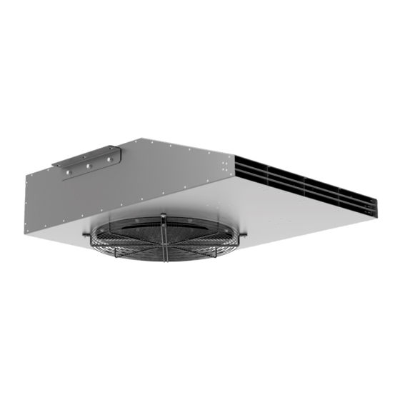
DESIGN AND FUNCTIONING The fan casing is made of polymer coated steel. The Terminal block protection grille on the air inlet side prevents ingress of Electric motor foreign objects. The deflecting plates on the pressure side Impeller ensure equal air distribution and boost air draft. Mounting brackets Depending on the fan modification it is equipped with a single-speed 4-pole motor or a double-speed 4/6- or 4/8-... -
Page 9: Connection To Power Mains
CONNECTION TO POWER MAINS DISCONNECT THE POWER SUPPLY PRIOR TO ANY OPERATIONS WITH THE UNIT. CONNECTION OF THE UNIT TO POWER MAINS IS ALLOWED BY A QUALIFIED ELECTRICIAN WITH A WORK PERMIT FOR THE ELECTRIC UNITS UP TO 1000 V AFTER CAREFUL READING OF THE PRESENT USER’S MANUAL. - Page 10 Wiring diagrams Wiring diagram for the fan operation Wiring diagram for the fan operation with high Model with low speed speed Single-speed -50N-4 ... -85N-4 ... -100N-4 ... ~400 V / 50 Hz ~400 V / 60 Hz Double-speed -50N-4/6 ... -85N-4/6 ...
- Page 11 ASYNCHRONOUS ELECTRIC MOTOR STARTING METHODS There are several methods for starting asynchronous squirrel-cage electric motors. The most common methods are: direct-on-line (DOL), with a soft starter (SS) or with a frequency converter (FC). Direct-on-line starting In case of direct-on-line starting (i.e. by connecting the motor to the electric mains with a simple line contactor), the motor starting time significantly increases due to high inertia of the impeller, which, in turn, results in high in-rush starting currents in the circuit.
-
Page 12: Commissioning
Let us review three variations of a heavy start: 1. The feed line performance is barely sufficient or insufficient to maintain the induced current. Typical symptoms: Upon starting the circuit breakers at the system input are tripped; the lights, certain relays and contactors go off, and the supply generator shuts down. -
Page 13: Technical Maintenance
TECHNICAL MAINTENANCE DISCONNECT THE UNIT FROM POWER SUPPLY BEFORE ANY MAINTENANCE OPERATIONS! PRIOR TO COMMENCING ANY TECHNICAL MAINTENANCE PUT UP A PROHIBITORY SIGN ON THE FAN STARTING PANEL: “DO NOT SWITCH ON! MEN AT WORK!” AVOID LIQUID SPILLS ON THE MOTOR! DO NOT USE AGGRESSIVE SOLVENTS AND SHARP OBJECTS FOR CLEANING! Disconnect the unit from power mains and wait for all rotating parts to be at a complete standstill before carrying out any technical maintenance and repair operations. - Page 14 POSSIBLE REASONS AND TROUBLESHOOTING Problem Possible reasons Troubleshooting The fan does not get started. No power supply. Check the automatic circuit breaker. Check the electric connections. Jammed motor. Carefully check the fan impeller for possible seizure and eliminate it, if necessary. If the impeller is in order, replace the electric motor.
- Page 15 The fan supplies less air than Wrong choice of the fan. Re-calculate the parameters and select the right fan. expected. Wrong direction of the impeller rotation If necessary, change the impeller rotation direction by direction. changing the phase sequence on the electric motor terminals.
-
Page 16: Storage And Transportation Regulations
STORAGE AND TRANSPORTATION REGULATIONS • Store the unit in the manufacturer’s original packaging box in a dry closed ventilated premise with temperature range from +5 °C to + 40 °C and relative humidity up to 70 %. • Storage environment must not contain aggressive vapors and chemical mixtures provoking corrosion, insulation, and sealing deformation. -
Page 17: Manufacturer's Warranty
MANUFACTURER’S WARRANTY The product is in compliance with EU norms and standards on low voltage guidelines and electromagnetic compatibility. We hereby declare that the product complies with the provisions of Electromagnetic Compatibility (EMC) Directive 2014/30/EU of the European Parliament and of the Council, Low Voltage Directive (LVD) 2014/35/EU of the European Parliament and of the Council and CE-marking Council Directive 93/68/EEC. - Page 18 www.ventilation-system.com...
-
Page 19: Certificate Of Acceptance
CERTIFICATE OF ACCEPTANCE Unit Type Impulse centrifugal fan Model ICF _______________________ Serial Number Manufacture Date Quality Inspector’s Stamp SELLER INFORMATION Seller Address Phone Number E-mail Purchase Date This is to certify acceptance of the complete unit delivery with the user’s manual. The warranty terms are acknowledged and accepted. - Page 20 V117EN-03...
Need help?
Do you have a question about the ICF Series and is the answer not in the manual?
Questions and answers