Table of Contents
Advertisement
Quick Links
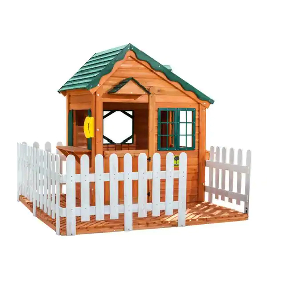
Mayfield Cottage
Assembly Instruction
Creative Cedar Designs
www.creativecedardesigns.com
Customer Service:
Please log onto our website and fill out
a request for missing / damaged parts.
email: custservice@creativecedardesigns.com
phone: 1-888-363-4967
Revision Date: 12/12/2019
Model: 9200
WARNING: CHOKING HAZARD
Unassembled parts may be a choking
hazard to children 3 years and younger.
The plastic bags that contain the hardware
may present a choking hazard to small
children. Please keep these bags and all
plastic bags out of the reach of children.
Do not allow children to play with them and
dispose of them immediately when empty.
CAUTION: Adult Assembly Required
Hardware contains small pieces with sharp
points. Keep parts out of the reach of
children until assembled. Parts of this product
can present dangers if improperly assembled
Advertisement
Table of Contents

Related Manuals for Creative Cedar Designs Mayfield Cottage


Summary of Contents for Creative Cedar Designs Mayfield Cottage
- Page 1 Mayfield Cottage Assembly Instruction Model: 9200 WARNING: CHOKING HAZARD Unassembled parts may be a choking hazard to children 3 years and younger. The plastic bags that contain the hardware may present a choking hazard to small Creative Cedar Designs children. Please keep these bags and all www.creativecedardesigns.com...
-
Page 2: Table Of Contents
Creative Cedar Designs CreativeCedarDesigns.com Table of Contents Letter to Customer Positioning Your Playcenter Tools Required for Assembly Helpful Installation Hints Maintenance Instructions Disposal Instructions CPSC Information Sheet Assembly Instructions Limited Warranty Warranty Claim Procedure Your owner’s manual should be read carefully... - Page 3 STOP…PLEASE READ!! IF YOU HAVE ANY QUESTION OR ARE MISSING A PART, PLEASE DO NOT CONTACT THE RETAILER THAT YOU PURCHASED THIS PRODUCT FROM. PLEASE VISIT www.creativecedardesigns.com OR CONTACT US DIRECTLY AT OUR OFFICE, 1-888-363-4967 WE WILL ANSWER YOUR QUESTIONS, OR HELP WITH WHAT YOU NEED. For more efficient service, please log onto our website at www.creativecedardesigns.com...
-
Page 4: Letter To Customer
Creative Cedar Designs equipment is recommended for use by children 3 to 10 years of age. Creative Cedar Designs structures are not intended for public use. Creative Cedar Designs does not warranty any of its residential structures subjected to commercial use. -
Page 5: Positioning Your Playcenter
The instructions and owner’s manual for your new Playcenter should be read in its entirety before assembly, to minimize problems and safety issues. We recommend reading the owner’s manual thoroughly after you have identified all of the parts for your Playcenter as discussed in the Helpful Installations Hints section below. -
Page 6: Helpful Installation Hints
Helpful Installation Hints 1. Depending on your experience, assembly of this Play set should take approximately 3 to 4 hours after inventory of parts. Therefore, we recommend you set aside a full day for assembly. 2. Identify all of the parts for your Playcenter. Empty each box and lay out boards so you can see each part. - Page 7 READ! VERY IMPORTANT! If you are missing parts or have questions regarding the installation of our quality product PLEASE email or contact us directly. Our trained staff will be happy to assist you. Please do not return the product to the retail store. Customer service hours: Monday thru Friday 9am to 5pm Saturday 9am to 2pm (During Season)
-
Page 8: Maintenance Instructions
Maintenance Instructions: 1. Check all nuts and bolts twice monthly during the usage season and tighten as required. (But not so tight that you crack the wood) It is particularly important that this procedure be followed at the beginning of each season. 2. -
Page 9: Cpsc Information Sheet
APPENDIX A Information on Playground Surfacing Materials: The following information is from the United States Consumer Product Safety Commission’s Information Sheet for playground surfacing material Also see the following website for additional information: www.cpsc.gov/cpscpub/pubs/323.html. X3. CONSUMER INFORMATION SHEET FOR PLAYGROUND SURFACING MATERIALS X3.1 The U.S. - Page 10 Customer Notes...
-
Page 11: Assembly Instructions
Basic Setup Dimensions Place the set on level ground, not less than 6ft (2M) from any structure or obstruction such as a fence, garage, house, overhanging branches, laundry lines or electrical wires. 6’ [1834mm] HEIGHT = 5’-6” [1684mm] Inside Dimension = 5’-3” [1604mm] @ Peak Height 3’-1”... - Page 12 Parts Identification 2A027 BACK GABLE (1 REQ.) 2A022 FRONT GABLE (1 REQ.) 2A025 PORCH ROOF (Rt.) 2A024 PORCH ROOF (Lt.) (1 REQ.) 2A021 RIGHT FRONT WALL (1 REQ.) 2A023 DOOR (1 REQ.) (1 REQ.) 2A026 BACK WALL 2A028 LEFT WALL 2A029 RIGHT WALL (1 REQ.) (1 REQ.)
- Page 13 Parts Identification 1 [25mm] 1 [25mm] 40 15/16 [1040mm] 40 15/16 [1040mm] LN18 SUB-FLOOR SLAT LN19 SUB-FLOOR SLAT (3 REQ.) (1 REQ.) 1 [25mm] 40 15/16 [1040mm] 1 [25mm] 1 [25mm] 15 9/16 [395mm] 29 1/8 [740mm] LN20 SUB-FLOOR SLAT LN21 SUB-FLOOR SLAT LN113 SUB-FLOOR SLAT (1 REQ.)
- Page 14 Parts Identification 7/16 [11mm] 44 3/4 [1137mm] LS65 WALL SLAT 7/16 [11mm] (1 REQ.) 22 1/16 [560mm] 38 15/16 [988mm] 7/16 [11mm] 11/16 [17mm] 38 15/16 [988mm] LS52 DOOR STOP LS41 WALL SLAT (1 REQ.) (1 REQ.) LS66 WALL SLAT (1 REQ.) 11/16 [17mm] 11/16 [17mm]...
- Page 15 Hardware Identification FW1/4 Fender Washer FW1/4 Flat Washer 1/4-20 x 2-1/2” Socket Head Bolt (30) (53) 1/4-20 x 2-1/4” Socket Head Bolt (18) Imperial Metric 1/4-20 T-Nut 1/4-20 x 1-3/4” Socket Head Bolt LW1/4 Lock Washer (10) 1/4" (57) (28) 1/2"...
- Page 16 Measuring hardware It is very important that you get the right hardware in the correct place when assembling the unit. You can use the ruler below to measure your hardware or you can compare the hardware to the hardware identification page. NOTES: 1) Do not include bolt head when measuring length of bolt.
- Page 17 Phase Sub-Floor Phase Hardware Assembly 1/4-20 x 1-3/4” Socket Head Bolt FW1/4 Flat Washer LW1/4 Lock Washer (10) (10) (10) WS1/8 X 3/4’’ Wood Screw (14) Phase Parts LN18 SUB-FLOOR SLAT LN21 SUB-FLOOR SLAT LP24 SUB-FLOOR SLAT (3 REQ.) (3 REQ.) (1 REQ.) LP25 SUB-FLOOR SLAT LP27 SUB-FLOOR SLAT...
- Page 18 Phase Phase Hardware Floor Square Att. WS1/8 x 2-1/8” Wood Screw WS1/8 x 1-5/8” Wood Screw (80) (48) Phase Parts STEP 1 LN113 SUB-FLOOR SLAT (6 REQ.) 2A032 FLOOR SQUARE (16 REQ.) LN114 SUB-FLOOR SLAT (6 REQ.) STEP 2 FLOOR SUPPORTS LN114 NOTE: MAKE SURE SQUARES ARE LN113...
- Page 19 Phase Phase Hardware Right Wall Prep. 1/4" Lock Washer 1/4-20 x 2-1/4" Socket Head Bolt 1/4" Fender Washer WS1/8 X 1 1/8" Wood Screw (10) 1/4-20 T-Nut Phase Parts NOTE: MAKE SURE UPRIGHTS ARE ORIENTED CORRECTLY. T-NUTS ARE INSERTED TOWARD THE INSIDE OF THE UNIT LJ104 UPRIGHT (RT) (2 REQ.)
- Page 20 Phase Phase Hardware Left Wall Prep. 1/4" Lock Washer 1/4” Fender Washer 1/4-20 x 2-1/4” Socket Head Bolt WS1/8 X 1 1/8" Wood Screw (12) 1/4-20 T-Nut Phase Parts NOTE: MAKE SURE UPRIGHTS ARE ORIENTED CORRECTLY. T-NUTS ARE INSERTED TOWARD THE INSIDE OF THE UNIT LJ105 UPRIGHT (LT) (2 REQ.)
- Page 21 Phase Left Wall Phase Hardware Assembly 1/4-20 x 2-1/4” Socket Head Bolt 1/4" Lock Washer 1/4" Fender Washer Phase Parts LT48 CORNER UPRIGHT (1 REQ.) LT70 CORNER UPRIGHT (1 REQ.) LEFT WALL FROM PHASE 4 1/4-20 x 2 1/4 Socket Head Bolt LOCK WASHER &...
- Page 22 Phase Front & Back Wall Phase Hardware Attachment 1/4-20 x 2-1/4” Socket Head Bolt 1/4" Fender Washer 1/4" Lock Washer WS1/8 X 1 1/8" Wood Screw Phase Parts LT36 BOTTOM WALL RAIL (1 REQ.) 1/4-20 x 2 1/4 Socket Head Bolt LOCK WASHER &...
- Page 23 Phase Left Wall Phase Hardware Attachment WS1/8 X 1 5/8" Wood Screw WS1/8 X 1 1/8" Wood Screw FRONT WALL NOT SHOWN FOR CLARITY Phase Parts RIGHT WALL STEP 1 BACK WALL LT63 BOTTOM WALL RAIL (1 REQ.) WS1/8 X 1 1/8" Wood Screw LEFT WALL ASSEMBLY 'LT63' IS ATTACHED TO WALL FRAME OF BACK WALL WITH...
- Page 24 Phase Front & Back Wall Phase Hardware Slat Attechment 1/4-20 x 1 Socket Head Bolt WS1/8 X 1" Wood Screw 1/4 Fender Washer 1/4 Lock Washer (10) Phase Parts LS65 WALL SLAT LS40 WALL SLAT (1 REQ.) (1 REQ.) LS66 WALL SLAT LS41 WALL SLAT (1 REQ.) (1 REQ.)
- Page 25 Phase Front & Back Gable Phase Hardware Attachment 1/4" Fender Washer 1/4" Lock Washer WS1/8 X 1" Wood Screw 1/4-20 x 2-1/2” Socket Head Bolt (10) Phase Parts 2A022 FRONT GABLE 2A027 BACK GABLE (1 REQ.) (1 REQ.) 1/4-20 x 2-1/2 Socket Head Bolt STEP 1 1/4 Lock Washer &...
- Page 26 Phase Shelf Phase Hardware Assembly WS1/8 X 2" Wood Screw (50) Phase Parts 6 5/8 [168mm] LS76 SHELF BOARD 2A034 WINDOW SILL (1 REQ.) (1 REQ.) 1 [25mm] LK77 SHELF GUSSET LS75 SHELF BOARD (3 REQ.) (1 REQ.) LH111 PLANTER BRD. LH109 PLANTER BRD.
- Page 27 Phase Shelf Phase Hardware Attachment WS1/8 X 2" Wood Screw (14) Phase Parts SHELF ASSEMBLIES FROM PREVIOUS PHASE CENTER SHELF AND FLUSH WITH WINDOW EDGE. ATTACH TO WALL WITH WOOD SCREWS THROUGH PRE-DRILLED HOLES ON THE INSIDE OF THE WALL AND INTO THE GUSSETS. (TYPICAL FOR RIGHT &...
- Page 28 Phase Brace Phase Hardware Attachment WS1/8 X 1" Wood Screw (32) Phase Parts TYPICAL INSIDE VIEW / LAYOUT FOR RIGHT & LEFT WALLS OTHER PARTS NOT SHOWN FOR CLARITY LT49 BRACE (8 REQ.) LT49 FLUSH FLUSH [52mm] FLUSH CENTER LINE FLUSH LT49 2 1 16 [52mm]...
- Page 29 Phase Fence Phase Hardware Assembly 1/4-20 x 2-1/2” Socket Head Bolt LW1/4 Lock Washer FW1/4 Flat Washer (10) 1/4-20 x 1-5/8” Socket Head Bolt (10) Phase Parts LT28 FENCE PICKET (9 REQ.) 1/4-20 x 2 1/2” SOCKET HEAD BOLT LT30 FENCE PICKET (1 REQ.) 1/4"...
- Page 30 Phase Place Cottage PLACE THE FLOOR ASSEMBLY IN THE SAFE AREA YOU HAVE CHOSEN (MAKE On Floor SURE THE AREA IS LEVEL). NOTE THE ORIENTATION OF THE COTTAGE DOOR IN RELATIONSHIP TO THE FLOOR ASSEMBLY WITH FENCE UPRIGHTS ATTACHED, AS SHOWN BELOW.
- Page 31 Phase Fence Rail Phase Hardware Assembly 1/4-20 x 1-1/4” Socket Head Bolt LW1/4 Lock Washer FW1/4 Flat Washer WS1/8 X 2 1/8" Wood Screw Phase Parts LT31 FENCE RAIL LT32 FENCE RAIL (2 REQ.) (2 REQ.) LT34 FENCE RAIL LT33 FENCE RAIL (2 REQ.) (2 REQ.) TYPICAL DETAIL...
- Page 32 Phase Fence Rail Phase Hardware Attachment 1/4-20 T-Nut 1/4-20 x 1-1/8" Socket Head Bolt LW1/4 Lock Washer FW1/4 Flat Washer WS1/8 X 1 1/8" Wood Screw (30) COTTAGE NOT SHOWN FOR CLARITY LT32 LT30 1/4-20 T-NUT 1/4-20 x 1 1/8" SOCKET HEAD BOLT 1/4"...
- Page 33 Phase Attach Cottage Phase Hardware to Fence 1/4-20 x 1-1/8 Socket Head Bolt LW1/4 Lock Washer FW1/4 Flat Washer WS1/8 X 1 1/8" Wood Screw Phase Parts (12) LT35 FENCE RAIL (2 REQ.) CAREFULLY POSITION / ALIGN COTTAGE WITH HOLES IN REAR FENCE RAILS 'LT31' THEN ATTACH 'LT35' AS SHOWN BELOW.
- Page 34 Phase L-Bracket Phase Hardware Attachment FW1/4 Fender Washer #14 x 3/4” Screw STUDY PLAN VIEW BELOW FOR (26) (26) BRACKET LOCATIONS Phase Parts (M002) GREEN L-BRACKET (SMALL) (13 REQ.) FENCE RAIL BRACKETS: CENTER BRACKETS VERTICALY ON RAILS AND ATTACH WITH (2) #14 X 3/4 TAPPING SCREWS & WASHERS EACH L-BRACKETS FENCE ENTRY BRACKETS: POSITION BRACKETS ON FLOOR AND...
- Page 35 Phase Fence Picket Phase Hardware Attachment WS1/8 X 1 1/8" Wood Screw (88) SIDE 4 SIDE 1 Phase Parts WS1/8 X 1 1/8" Wood Screw LT29 FENCE PICKET (22 REQ.) SIDE 2 SIDE 3 2-3/32’’ 2-3/32’’ 2-3/32’’ 2-3/32’’ 2-3/32’’ 2-3/32’’ FLOOR FLOOR SURFACE...
- Page 36 Phase Roof Phase Hardware Attachment WS1/8 X 1 3/8" Wood Screw (28) FLOOR & FENCE NOT SHOWN FOR CLARITY Phase Parts LT61 ROOF TRIM (2 REQ.) LT62 ROOF TRIM (2 REQ.) PEEK DETAIL 2A031 LARGE ROOF SECTION 2A030 SMALL ROOF SECTION (1 REQ.) (1 REQ.) WS1/8 X 1 3/8"...
- Page 37 Phase Dormer Phase Hardware Assembly WS1/8 X 1 3/8" Wood Screw WS1/8 X 1" Wood Screw (26) Phase Parts LS102 DORMER ROOF BRD. LS98 DORMER BRACE LR96 DORMER GABLE LR92 DORMER WALL (LT) (1 REQ.) (1 REQ.) (1 REQ.) (1 REQ.) LR97 DORMER BRACE LS101 DORMER ROOF BRD.
- Page 38 Phase Accessory Phase Hardware Attachment WS1/8 X 5/8" Wood Screw WS1/8 X 1" Wood Screw (20) FLOOR & FENCE #14 x 3/4” Screw NOT SHOWN FOR CLARITY LT49-1 WINDOW SUPPORT. (1 REQ.) Phase Parts LT49-1 6’’ INSERT CENTER SUPPORT FOR WINDOW FRAMES. (PF2990) WINDOW FRAME (PHN867) PLASTIC PHONE (2 REQ.)
- Page 39 Phase Porch Roof & Phase Hardware 1/4” Lock Washer Door Stop 1/4” Flat Washer 1/4-20 T-Nut 1/4-20 x 1-1/2” Socket Head Bolt ROOF & FENCE WS1/8 X 1 1/8" Wood Screw NOT SHOWN FOR CLARITY Phase Parts 2A024 2A025 LS52 DOOR STOP 2A025 PORCH ROOF (Rt.) 2A024 PORCH ROOF (Lt.) (1 REQ.)
- Page 40 Phase Phase Hardware Porch Roof WS1/8 X 1 3/8" Wood Screw WS1/8 X 2 1/8" Wood Screw ROOF, FLOOR & FENCE WS1/8 X 1" Wood Screw NOT SHOWN FOR CLARITY (14) Phase Parts LQ57 LQ57 SOFFIT BOARD LQ58 SMALL GABLE (1 REQ.) (1 REQ.) LQ58...
- Page 41 Phase Door & Placard Attachment Phase Parts CreativeCedarDesigns.com ID-TAG w/ HARDWARE (1) REQ. DOOR HINGE (93BHNG) w/ HARDWARE (2) REQ. 2A023 DOOR DOOR KNOB (DRKNOB) 3/16" DRILL BIT (1 REQ.) w/ HARDWARE (1) REQ. DOOR KNOB 3/16 x 1” SCREW LOCK WASHER &...
- Page 42 Phase Anchoring Phase Parts ASSEMBLY COMPLETE! MAKE SURE TO TIGHTEN ALL HARDWARE (BP001-B) ANCHOR PACK w/ HDW (2 REQ.) NOTE: DO NOT OVER TIGHTEN HARDWARE. STAKE STAKE TO AVOID SPLITTING WOOD, PRE-DRILL ALL STAKE HARDWARE. FLAT WASHER 1-1/2’’ LAG BOLT METAL STRAP ANCHOR...
-
Page 43: Limited Warranty
LIMITED WARRANTY Creative Cedar Design offers many fun, interactive, and safe play centers. We only guarantee the original purchaser that this product is free of defects in materials for 30 days from the date of purchase, with the product registration card and the dated receipt as proof of purchase. Under this warranty there will be a replacement for the defective component of the play center. -
Page 44: Warranty Claim Procedure
3. Photos of warranted parts and of the entire play system. If any of the above steps are not completed, there may be delays in the completion of your claim, or possibly warranty cancellation. Mail information to: Creative Cedar Designs 2700 Riverside Dr Chattanooga, TN 37406 Or email at custservice@creativecedardesigns.com...
Need help?
Do you have a question about the Mayfield Cottage and is the answer not in the manual?
Questions and answers