
Related Manuals for WEG UR11 Series


Summary of Contents for WEG UR11 Series
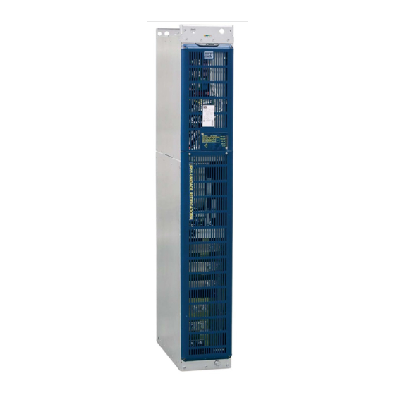
- Page 1 Motors | Automation | Energy | Transmission & Distribution | Coatings Rectifier Unit Unidad Rectificadora Unidade Retificadora UR11 User's Manual Manual del Usuario Manual do Usuário...
- Page 2 UR11 RECTIFIER UNIT MANUAL Series: UR11 Language: English Document: 10001149720 / 01 Models: 1140 A / 380...480 V 893 A / 500…600 V 811 A / 660…690 V 03/2015...
- Page 3 Summary of Revisions Version Revision Description First edition. Updating of the figures and general revision.
-
Page 4: Table Of Contents
Contents 1 SAFETY INSTRUCTIONS ..............1-1 1.1 SAFETY WARNINGS IN THE MANUAL ............1-1 1.2 SAFETY WARNINGS IN THE PRODUCT ............1-1 1.3 PRELIMINARY RECOMMENDATIONS ............1-2 2 GENERAL INSTRUCTIONS .............. 2-1 2.1 ABOUT THE MANUAL ................. 2-1 2.2 TERMS AND DEFINITIONS USED IN THE MANUAL ........2-1 2.3 ABOUT THE UR11 .................. - Page 5 Contents 5 TROUBLESHOOTING AND MAINTENANCE ........5-1 5.1 OPERATION OF THE FAULTS AND ALARMS ..........5-1 5.2 FAULTS, ALARMS, AND POSSIBLE CAUSES ..........5-1 5.3 SOLUTIONS FOR THE MOST FREQUENT PROBLEMS ........5-3 5.4 INFORMATION FOR CONTACTING TECHNICAL SUPPORT ......5-3 5.5 PREVENTIVE MAINTENANCE ..............
-
Page 6: Safety Instructions
Safety Instructions 1 SAFETY INSTRUCTIONS This manual provides information for the proper installation and operation of the Rectifier Unit UR11 developed to perform the rectification for the CFW-11M product line. Only trained and qualified personnel should attempt to install, start-up, and troubleshoot this type of equipment. 1.1 SAFETY WARNINGS IN THE MANUAL The following safety warnings are used in this manual: DANGER! -
Page 7: Preliminary Recommendations
If needed, touch first the grounded metal frame or wear an adequate ground strap. Do not perform a withstand voltage test on any part of the rectifier unit! If needed, please, consult WEG. NOTE! Rectifiers may cause interference in other electronic devices. Follow the recommendations listed in chapter 3 INSTALLATION AND CONNECTION on page 3-1, to minimize these effects. -
Page 8: General Instructions
RACK 2/RACK 3 mounting guide. The mounting guide is available in the CD-ROM provided with the rectifier unit or it can be downloaded from WEG website at - www.weg.net. 2.2 TERMS AND DEFINITIONS USED IN THE MANUAL Normal Duty Cycle (ND): inverter duty cycle that defines the maximum continuous operation current (I... - Page 9 General Instructions Pre-charge Circuit: transitional stage of the UR11 operation, which starts when the power is applied to the input phases and ends with the complete charging of the DC link capacitors of the inverter connected to its output. This step is controlled by the UR11, which performs the loading of DC link capacitors through a voltage ramp with limited current, avoiding high current spikes on the inverter startup.
- Page 10 General Instructions Switching Frequency: frequency of the IGBTs switching in the inverter bridge, normally expressed in kHz. Heatsink: metal device designed to dissipate the heat generated by the power semiconductors. Amp, A: ampères. °C: celsius degree. AC: alternated current. DC: direct current. CFM: Cubic Feet per Minute;...
-
Page 11: About The Ur11
General Instructions 2.3 ABOUT THE UR11 The rectifier unit UR11 provides DC voltage to feed the CFW-11M inverters. The UR11 can also be used to provide power to other devices that require DC link voltage. The main feature of this product is the two built-in complete semi-controlled rectifier bridges, which have the advantages presented next: DC link pre-charge control, provided by the control of the thyristors firing angle through a microcontroller: the pre-charge provides a linear voltage ramp, avoiding high currents and eliminating the pre-charge circuit... - Page 12 General Instructions +UD, -UD UR11 R1, S1, T1 R2, S2, T2 F1, F2, F3 F4, F5, F6 Power supply 3∼ Figure 2.2 - Example of diagram of a 12 pulse configuration with one rectifier unit The UR11 can be provided together with the complete panel (AFW-11M) or as a stand-alone product to be assembled in a panel.
- Page 13 General Instructions Power section fans UR11 220 V Ext. Cabinet aux. power supply DC Bus (DC Link) Rectifier Power supply NTCs Rectifier Feedback: Feedback: - DC link voltage - input voltage - heatsink temperature CPC11 POWER Supply board and thyristor control with the 32 CONTROL bits "RISC"...
- Page 14 General Instructions A...F Heatsink fans RCS4 CLR1 +UD -UD Obs.: 6 x RCS4 External 220 V CPC11 CPC11 XC15A XC15A 6 x TD570N Figure 2.5 - UR11 general internal diagram: power connections +24 Vdc XC10 XC101 External +24 Vdc XC16 NTC _ R XC3R CPC11...
-
Page 15: Identification Label For The Ur11
2.4 IDENTIFICATION LABEL FOR THE UR11 There are two identification labels, one located at the front cover and another inside the UR11 enclosure, close to the fans. Manufacturing date UR11 Model WEG part number Maximum surrounding air temperature UR11 Net weight Serial number... -
Page 16: Receiving And Storage
Table 7.1 on page 7-2. Table 2.1 - Smart code Rectifier Model Refer to chapter 7 TECHNICAL SPECIFICATIONS on page 7-1 for a list of models for the UR11 series and the rectifiers technical specification. Example UR11 1140 Field Market identification WEG Rectifier... - Page 17 General Instructions Check the following items once the rectifier is delivered: Verify that the product identification label corresponds to the model number on your purchase order. Inspect the product for external damaging during transportation. Report any damage immediately to the carrier that delivered your product. If the products were note installed immediately, store them in a clean and dry place (temperature between -25 °C and 60 °C (77 °F and 140 °F)) with a cover in order to avoid the contamination with dust.
-
Page 18: Installation And Connection
Installation and Connection 3 INSTALLATION AND CONNECTION This chapter provides information on installing and wiring the UR11. The instructions and guidelines listed in this manual shall be followed in order to guarantee personnel and equipment safety, as well as the proper operation of the rectifier. -
Page 19: Mechanical Installation
Installation and Connection Table 3.1 - Currents and configuration in 380 / 480 V Number of Nominal Current (A) Power Units UR11 in Parallel 1140 1710 1468 2280 1957 2850 2446 Table 3.2 - Currents and configuration in 500 / 600 V Number of Nominal Current (A) Power Units... - Page 20 Installation and Connection ∅ 22.5 mm (0.89 in) hoisting eyes - weight 286 Kg (630.52 lb) Figure 3.1 - UR11: hoisting eyes Figure 3.2 - Mounting of the UR11 side by side without lateral spacing UR11 | 3-3...
- Page 21 Installation and Connection Panel fan (when required) [5.9] Ventilation openings on frontal panel surface Figure 3.3 - Ventilation clearances in mm [in] The total air outflow of the power unit is 1150 m³/h (320 l/s; 677 CFM). It is recommended an outflow of 1350 m³/h (375 l/s;...
- Page 22 Installation and Connection The UR11 wheels facilitate its insertion into and withdrawal from the panel (Figure 3.4 on page 3-4). Figure 3.5 - Fixing holes of the rectifier unit Supports for top fixing of the drive 14.5 14.5 100.5 100.5 Figure 3.6 - Supports for top fixing (mm [in]) UR11 | 3-5...
-
Page 23: Electrical Installation
The interconnection between the UR11 output and the DC bus can be done with flat braided cables sized to withstand the UR11 output DC current (see specifications at Table 7.1 on page 7-2). The Figure 3.7 on page presents an example of flat braided cable used by WEG. 3-6 | UR11... -
Page 24: Fuses
3-13. ATTENTION! The braided cable presented at Figure 3.7 on page 3-7, used by WEG, was designed to withstand half the UR11 output DC current (see UR11 specifications at Table 7.1 on page 7-2). Therefore, two parallel braided cables are necessary for each connection (+UD and -UD). It is necessary to consult the braided cable manufacturer for proper sizing in case it is desired to use only one braided cable per connection. - Page 25 900 A 900 A Figure 3.8 - Example of 6 pulse configuration with one rectifier unit Table 3.4 on page 3-8 presents WEG values according to the configuration presented at Figure 3.8 on page 3-8 (6 fuses per UR11). Table 3.4 - Recommended Fuses...
-
Page 26: Terminals Recommended For Power Cables
Installation and Connection 3.4.4 Terminals Recommended for Power Cables Table 3.5 - (a) and (b) - Recommended cable lugs for power connections (a) Cable gauges in mm² Wire Size Stud Number of Manufacturer Ring Lug, P/N Crimping (installation) Tool P/N Size Crimps Hollingsworth... -
Page 27: Operation As 6 Pulse Rectifier
Installation and Connection 3.4.5.1 Operation as 6 Pulse Rectifier 24 Vdc ext. 24 Vdc ext. 24 Vdc ext. 24 Vdc, RL1/RL2/RL3 24 Vdc, RL1/RL2/RL3 24 Vdc, RL1/RL2/RL3 +/- 10 %, output relays +/- 10 %, output relays +/- 10 %, output relays 300 mA, 300 mA,... -
Page 28: Operation As 12 Pulse Rectifier
Installation and Connection 3.4.5.2 Operation as 12 Pulse Rectifier 24 Vdc ext. 24 Vdc ext. 24 Vdc ext. 24 Vdc, RL1/RL2/RL3 24 Vdc, RL1/RL2/RL3 24 Vdc, RL1/RL2/RL3 +/- 10 %, output relays +/- 10 %, output relays +/- 10 %, output relays 300 mA, 300 mA,... - Page 29 Installation and Connection 24 Vdc ext. 24 Vdc ext. 24 Vdc, RL1/RL2/RL3 24 Vdc, RL1/RL2/RL3 +/- 10 %, output relays +/- 10 %, output relays 300 mA, 300 mA, external external power power UR11 UR11 supply supply (PE) (PE) 220 V ext. 220 V ext.
-
Page 30: Ur11 Connections
Installation and Connection 3.4.6 UR11 Connections 3.4.6.1 Panel Layout and Connections Inverter Power supply (PE) Figure 3.13 - Example of adequate panel installation layout Figure 3.13 on page 3-13 presents the adequate installation layout for three parallel UR11 rectifier units. 3.4.6.2 Power Connections ATTENTION! The power supply that feeds the rectifier must have a grounded neutral. - Page 31 Installation and Connection NOTE! The voltage must be compatible to the rectifier rated voltage. Refer to item 3.4.6.4 Control Connections on page 3-18 for the configuration of the UR11 rated operation voltage. The fastening of the UR11 output connections is done with four M12 x 25 bolts (tightening torque: 60 N.m.), as presented at Figure 3.14 on page 3-14.
- Page 32 Installation and Connection Output bar " R1 " Output bar " R2 " Output bar " S1 " Output bar " S2 " Output bar " T2 " Output bar " T1 " 20 [0.79] 40 [1.57] 40 [1.57] 20 [0.79] Figure 3.15 - UR11 output bus bar, power supply output connections (mm [in]) Use two cables in parallel, with the recommended gauge indicated in the Table 3.6 on page...
-
Page 33: Grounding Connections
Installation and Connection 220 V input connector Figure 3.16 - Fans supply terminals: 220 V / 4 A 3.4.6.3 Grounding Connections ATTENTION! The neutral conductor of the network must be solidly grounded; however, this conductor must not be used to ground the rectifier. ATTENTION! The rectifier must be obligatorily connected to a protective ground (PE). -
Page 34: Network
Installation and Connection Front grounding with M12 bolt Figure 3.17 - UR11 ground connection point 3.4.6.3.1 IT Network ATTENTION! In order to use the rectifier unit in IT networks (not grounded or grounded via high impedance) or grounded delta networks (delta corner earth), it is necessary to disconnect the grounding cable located at the CLR1 board of the XE1 connector and connect it to the XIT connector located in the same board. -
Page 35: Control Connections
Installation and Connection The UR11 rectifier series was developed to be used in application with the CFW-11M (Modular Drive) inverter series, which can be used in IT networks without modifications. In these cases consider the following: The phase to ground or isolation fault indication must be processed by the user to indicate the failure occurrence and/or block the inverter operation. - Page 36 Installation and Connection Table 3.9 - XC2 Connector signals of the CIR11 Standard Function Specifications RL1 digital output with DC bus OK function (UDC1 & Contacts rating: 1 A. UDC2 OK). Maximum voltage: 240 Vac. - UDC1: DC bus of the rectifier bridge 1. NC - normally closed contact.
-
Page 37: Typical Connections
Installation and Connection The DIP switch S1:1 is set to OFF and the DIP switch S1:2 is set to ON as factory default. Follow instructions below for the proper installation of the control wiring: Wire gauge: 0.5 mm² (20 AWG) to 1.5 mm² (14 AWG). Maximum tightening torque: 0.5 N.m (4.50 lbf.in). - Page 38 Installation and Connection UR11 UC11 (CFW11M) IPS1 DIM1 (P0832 = 6) DIM2 (P0833 = 4) CIR11 GND_+24 V +24 V * NO - normally open contact. C - common. NC - normally closed contact. Figure 3.22 - Application example with active high signal at the DIs of the CFW-11M UR11 UC11 (CFW11M) IPS1...
- Page 39 Installation and Connection NOTE! Make sure the CFW-11M inverter has the 2.0x software version or above. For more details, refer to the "CFW-11M user manual" and the "CFW-11 programming manual". The examples of Figure 3.22 on page 3-21 Figure 3.23 on page 3-21 show that the DIM1 and DIM2 digital inputs are set to "Without External Rectifier Fault"...
-
Page 40: Installation According To The European Directive Of Electromagnetic Compatibility
Installation and Connection 3.5 INSTALLATION ACCORDING TO THE EUROPEAN DIRECTIVE OF ELECTROMAGNETIC COMPATIBILITY ATTENTION! The conformity with European directives of electromagnetic compatibility "EMC Directive 2004/108/EC" also depends on the inverters connected to the UR11 output. Always follow the installation instructions as presented in the inverter manual. 3.5.1 Conformal Installation with the CFW-11M When the CFW-11M is installed according to the user's manual instructions presented at chapter 3.5... -
Page 41: Emission And Immunity Levels
Installation and Connection Note: a professional is a person or organization familiar with the installation and/or commissioning of inverters, including their EMC aspects. Category C3: inverters with a voltage rating less than 1000 V and intended for use in the Second Environment only (not designed for use in the First Environment). - Page 42 Installation and Connection ATTENTION! Use the listed filters only in lines with a solidly grounded neutral point. Do not use them in IT networks, lines that are not grounded or grounded via a high impedance. ATTENTION! The filters presented in the CFW-11M user's manual are for low voltage power supply. When the filter is to be used in the primary of the input power transformer (in case the UR11 is set for 12 pulse rectifier operation) and its input voltage is medium or high voltage, contact the filter manufacturer (EPCOS or other) in order to check possible configurations.
- Page 43 Installation and Connection 3-26 | UR11...
-
Page 44: First Time Power-Up And Start-Up
First Time Power-Up and Start-Up 4 FIRST TIME POWER-UP AND START-UP This chapter describes how to: Check and prepare the rectifier before power-up. Power-up the rectifier and check the result. Set the rectifier for the operation with the power supply chosen for the application. 4.1 PREPARE FOR START-UP The rectifier must have been already installed according to the recommendations listed in chapter 3 INSTALLATION... - Page 45 First Time Power-Up and Start-Up 6. Observe the existence of faults/alarms at the relay outputs and LEDs. In case of any fault or alarm, verify the possible causes and solve the problem. 7. Check the input current of each rectifier unit with a current meter. The current must be smaller than 5 % the ND rated current as the rectifier is under no load.
-
Page 46: Troubleshooting And Maintenance
Troubleshooting and Maintenance 5 TROUBLESHOOTING AND MAINTENANCE This chapter: Lists all faults and alarms that may occur. Indicates the possible causes of each fault and alarm. Lists most frequent problems and corrective actions. Presents instructions for periodic inspections and preventive maintenance in the equipment. 5.1 OPERATION OF THE FAULTS AND ALARMS When the high temperature alarm is detected: The status LED "TEMP_ALARM"... - Page 47 Troubleshooting and Maintenance Table 5.1 - Operation of faults and alarms Name Description Inputs. +24 Vdc. +24 Vdc power supply of the CIR11 board. R, S, T. R1, S1, T1, R2, S2 and T2 input power connections. Pre-charge. Pre-charge status: "Not-performed", "In progress" or "Completed". Temperature.
-
Page 48: Solutions For The Most Frequent Problems
The electronic boards have electrostatic discharge sensitive components. Do not touch the components or connectors directly. If needed, first touch the grounded metallic frame or wear a ground strap. Do not perform any withstand voltage test! If needed, consult WEG. UR11 | 5-3... - Page 49 Troubleshooting and Maintenance The rectifiers require low maintenance when properly installed and operated. Besides the periodic cleaning of the heatsink fins, it is recommended to exchange the fans after 50.000 hours operation. Figure 5.1 on page 5-4 shows the UR11 fans exchanging procedure. It is recommended periodic inspections to be performed every 6 months after rectifier start-up.
-
Page 50: Cleaning Instructions
Troubleshooting and Maintenance 5.5.1 Cleaning Instructions When it becomes necessary to clean the rectifier, follow the instructions below: Ventilation system: Cut off the rectifier supply and wait 10 minutes. Remove the dust accumulated at the ventilation inlets with a plastic brush or a flannel. Remove the dust accumulated on the heatsink fins and on fan blades using compressed air. - Page 51 Troubleshooting and Maintenance 5-6 | UR11...
-
Page 52: Option Kits And Accessories
Option Kits and Accessories 6 OPTION KITS AND ACCESSORIES This chapter presents: The accessories that can be incorporated to the rectifiers. Instructions for the installation, operation, and programming of the accessories are described in their own manuals and are not present in this chapter. 6.1 OPTION KITS The UR11 rectifier unit does not have any option kits. - Page 53 Option Kits and Accessories 6-2 | UR11...
-
Page 54: Technical Specifications
Technical Specifications 7 TECHNICAL SPECIFICATIONS This chapter describes the technical specifications (electrical and mechanical) of the UR11 Rectifier Unit. 7.1 POWER DATA Power supply: Maximum rated input voltage: 480 V for 380...480 V models, 600 V for 500...600 V models and 690 V for 660...690 V models, up to 2000 m altitude. -
Page 55: Electrical / General Specifications
- Environment with pollution degree 2 (according to EN50178 and UL508C). (4) The motor ratings are merely a guide for 440 V (400 V line), 575 V (500 V line) and 690 V (600 V line), IV pole WEG motors. The adequate rectifier sizing shall be based on the rated current of the motor used. -
Page 56: Codes And Standards
Technical Specifications 7.2.1 Codes and Standards SAFETY STANDARDS. UL 508C - power conversion equipment. UL 8340 - insulation coordination including clearances and creepage distances for electrical equipment. EN61800-5-1 - safety requirements electrical, thermal and energy. EN 50178 - electronic equipment for use in power installations. EN 60204-1 - safety of machinery. - Page 57 Technical Specifications 46.3 [1.82] [9.05] 579.1 [22.8] 77.5 556.7 [21.92] 510.7 [20.11] Figure 7.1 - UR11 dimensions in mm [in] 7-4 | UR11...
Need help?
Do you have a question about the UR11 Series and is the answer not in the manual?
Questions and answers