REID LIFTING PORTA-GANTRY 5000 Assembly & Operation
Hide thumbs
Also See for PORTA-GANTRY 5000:
- Assembly & operation manual (24 pages) ,
- Assembly & operation manual (19 pages)
Table of Contents
Advertisement
Quick Links
Advertisement
Table of Contents

Related Manuals for REID LIFTING PORTA-GANTRY 5000


Summary of Contents for REID LIFTING PORTA-GANTRY 5000
- Page 1 ASSEMBLY VIDEO Assembly & Operation www.reidlifting.com...
-
Page 2: Table Of Contents
No. 1 in lightweight, portable, safe lifting solutions CONTENTS ASSEMBLY INSTRUCTIONS INTRODUCTION • Mechanical Aid Assembly • Manual Assembly CORRECT OPERATION • Beam Height Adjustment • Intended Use • A-Frames with Geared Handwheel • Inspection Prior to Initial Operation • A-Frame with Ratchet System •... -
Page 3: Introduction
INTRODUCTION All users must read these operating instructions carefully prior to the initial operation. These instructions are intended to acquaint the user with the machine/hoist and enable him/her to use it to the full extent of its intended capabilities. The operating instructions contain important information on how to handle the gantry in a safe, correct and economic way. -
Page 4: Correct Operation
No. 1 in lightweight, portable, safe lifting solutions CORRECT OPERATION should comply to EN1496:2017 or equivalent. Intended Use Only ONE person/load may be attached to ONE trolley in accordance with the WLLs. The PORTA-GANTRY is intended to be used for the The gantry has an up-rated capacity for personnel lifting of goods or the lifting of persons, or for providing positioning. -
Page 5: Notes For Correct Usage
NOTES FOR CORRECT USAGE conductivity, cutting, abrasion, climatic exposure and the effect of offset forces as a result of pendulum falls • We recommend the use of load-sensing or overload • The gantry is not to be moved under load except protection devices on all lifts when a Competent Person or authority approves •... -
Page 6: Attaching The Load
No. 1 in lightweight, portable, safe lifting solutions should be disassembled. If disassembling is not It is recommended that once inspected the device is possible, the gantry should be tied to a rigid marked with the date of next inspection. structure to avoid overturn Inspections are instigated by the user. -
Page 7: Atex
Any different or exceeding use is considered 2: Category 2 – High safety for use in Zone 1 incorrect and REID Lifting Ltd will not accept any GD: For use in gas (G) & dust (D) atmospheres responsibility for damages resulting from false T6:Temperature class –... -
Page 8: Atex - Static Electricity
No. 1 in lightweight, portable, safe lifting solutions REID recommend the use of corrosion resistant tools and the height adjustment ratchet (if fitted). Where when assembling the PORTA-GANTRY system to there is sign of any rust deposits on the aluminium prevent the possibility of any sparks. -
Page 9: Assembly Instructions
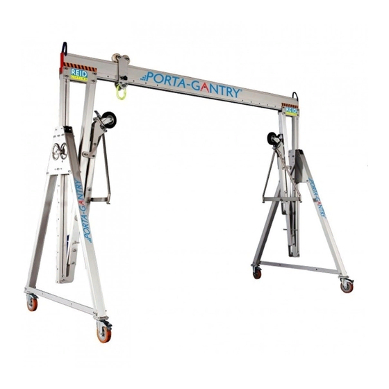
ASSEMBLY INSTRUCTIONS Gloves Protective footwear Hard hat N.B. Appropriate PPE should be worn: The PORTA-GANTRY and its constituent components are described in the image below. Trolley Beam Cheek Plate Bolts, Nuts & Washers Adjustable Upright Strut ‘Trap’ Plate Strut Handle Hockey Stick Lockable Castors Leg Brace... - Page 10 No. 1 in lightweight, portable, safe lifting solutions PORTA-GANTRY system delivered flat packed on Gantry Tool Set (supplied as an option): a pallet: • Ratchet handle 1/2” sq drive • 2 x A-Frames • 24mm socket • 1 Trolley • 24mm combination spanner (Stabiliser legs –...
- Page 11 Bolt 2 Lock castors in Bolt 1 orientation shown: Cheek Plates bolts 1 and 2 Apply the castor brakes Put brakes on only with protective footwear ensuring that the castors are in the orientation shown. Do not use hands Lay the two A-Frames a beam length apart on a Offer one end of the beam to the rear bolt-hole on flat surface in line with each other with the castor the cheek-plate (Bolt 1) and insert a bolt.
- Page 12 No. 1 in lightweight, portable, safe lifting solutions Thread beam trolley over the other end of the Offer opposite side of beam to the rear bolt-hole beam and lock with friction brake at on the cheek-plate (Bolt 1) and insert bolt. approximately centre position.
-
Page 13: Mechanical Aid Assembly
Mechanical Aid Assembly Spare Bolt Mechanical Aid Move trolley to last beam hole on side of A-frame to Attach chain block to trolley master-link and be assembled and insert spare bolt into beam, attach the lifting chain to the mechanical aid, as between trolley and A-frame to be assembled, as shown. -
Page 14: Manual Assembly
No. 1 in lightweight, portable, safe lifting solutions Manual Assembly If mechanical aid assembly not possible proceed as follows: Secure trolley at opposite end of beam to be assembled and secure by tightening trolley knob. With the help of 2 (or 3) people, scissor the beam and A-Frame into position (using the first bolt as a hinge until A-frame assembly perpendicular to beam). - Page 15 Insert and tighten the final beam bolt. If the hoist is not already attached to the suspension point on the trolley, do so now (using N.B. The use of a suitable platform ladder may stepladder if height setting requires). be advisable to reach the bolt-hole. If this is not safe, disassemble the gantry and re-start, adding the hoist prior to raising the A-Frames - Step 9.
-
Page 16: Beam Height Adjustment
No. 1 in lightweight, portable, safe lifting solutions Beam Height Adjustment With Geared Handwheel: Two Person Operation is Recommended – one on each A-Frame working concurrently. For taller A-Frames suitable platform ladder should be used to operate the gearwheel at an ergonomic height. Decide on the height required (always use the lowest setting for the work in hand) Ensure the castor brakes are on... - Page 17 With Ratchet System: Two Person Operation Recommended – one on each A-Frame working concurrently. Always wear gloves when using this item. Decide on the height required (always use the lowest setting for the work in hand) Ensure the claw-hook at the end of ratchet strap is positively engaged with the bottom hole on A-Frame upright Remove lower bolt on trap plate...
-
Page 18: Medium Or Small A-Frame With No Gearing Fitted
No. 1 in lightweight, portable, safe lifting solutions Medium or Small A-Frame with no Beam height gearing fitted: adjustment bolts (2 bolts on Adjust the upright position at one A-Frame each upright) (a 2 man operation – one on the bolts and one on the upright) by removing 2 x upright securing Tighten all bolts to bolts, moving the upright to the appropriate... - Page 19 Stabiliser Leg Configurations Minimum Two Person Operation Recommended The A-Frames of WLL 5000kg capacity need to be handled with care and respect. The centre of gravity is high on the intermediate (I) and tall (T) models and should have a Stabiliser Leg fitted. There are two safe modes of handling depending on the environment.
- Page 20 No. 1 in lightweight, portable, safe lifting solutions Changing from Wheelbarrow to Vertical Configuration Two Person Operation is Recommended - Always wear gloves when using this item. With A-Frame on its back, unpin Wishbone Unpin castor link plate from A-Frame Strut, Tie Bar from the Stabiliser Leg ensuring the weight of the Stabiliser Leg is held to help prevent the trapping of hands or fingers...
-
Page 21: Vertical Configuration
Manoeuvring A-Frame in Vertical Configuration One Person Operation Recommended for Manoeuvring - Always wear gloves when using this item. With A-Frame on its back, ensure A-Frame Castor Wheels are locked in position. Put brakes on only with protective footwear DO NOT USE HANDS Ensure Stabiliser Leg is correctly and safely assembled in the vertical configuration (see Changing from Wheelbarrow to... -
Page 22: Wind Up Jack Legs Option (Wujl)
No. 1 in lightweight, portable, safe lifting solutions Wind Up Jack Leg Option (WUJL) WUJL option may be fitted to the gantry – this gives Having performed the lifting operations, return fine adjustment in the height setting (300mm total lift gantry to it’s castors and park the jack leg as in Fig. -
Page 23: Porta-Gantry Range
PORTA-GANTRY RANGE Unique portable gantry system that can safely lift up to 5000kg, with manual assembly on just 4 bolts. NOTE - Beam Height Adjustment NOTE - Beam Height Adjustment The height of each gantry beam is easily adjusted by the release of 2 bolts on each upright and can be easily and safely raised into position by increments of 200 or 150mm depending on product. -
Page 24: Detailed Dimensions
No. 1 in lightweight, portable, safe lifting solutions PORTA-GANTRY RANGE | Detailed Dimensions(mm) D max D min H max H min A-Frame Castor Max height Min height to Max height to Max height to Min height to Trolley roller Height increment Width Weight (kg to lifting eye... -
Page 25: Porta-Gantry 500-3000
PORTA-GANTRY 500-3000 PORTA-GANTRY RAPIDE Unique lightweight, portable gantry system with WLL Unique, ultra-lightweight, portable, rapid assembly gantry system WLL up to 1000kg for goods and 250kg up to 3000k. for personnel, designed for rapid deployment, confined space/work at height applications, personnel lifting and fall protection up to 3 persons. -
Page 26: Quality & Safety
ACCREDITATIONS Conformité Européenne (CE) Quality and safety are key themes throughout this document and the REID Lifting ethos. It is with this in REID Lifting’s products have been designed, tested and mind that we have undertaken external accreditations approved (as appropriate) by the Conformité Européenne. -
Page 27: Inspection Record
INSPECTION INSPECTION RECORD * Insert data from serial numbers found on product into table below Product number(s)* A Serial number(s)* B WLL* C Year of manufacture* D Name of user Date of purchase Date of first use Periodic Examination and Repair History Date Inspected by Pass/Fail... - Page 28 All information herein is copyright protected by REID Lifting Ltd. All company and product names are Trade Mark and Trade Name protected and all REID Product IPR is protected under Patents, Patents Pending and/or Design Rights. Printed using environment friendly processes and materials...
Need help?
Do you have a question about the PORTA-GANTRY 5000 and is the answer not in the manual?
Questions and answers