REID LIFTING PORTAGANTRY 500 Assembly & Operation Manual
Hide thumbs
Also See for PORTAGANTRY 500:
- Assembly & operation (24 pages) ,
- Assembly & operation manual (24 pages) ,
- Assembly & operation manual (19 pages)
Table of Contents
Advertisement
Quick Links
Advertisement
Table of Contents

Related Manuals for REID LIFTING PORTAGANTRY 500


Summary of Contents for REID LIFTING PORTAGANTRY 500
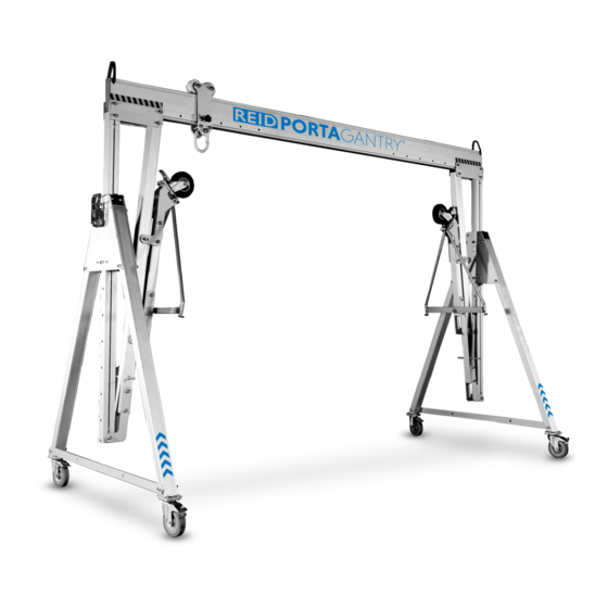
- Page 1 PORTAGANTRY 500-3000 Assembly & Operation Guide REIDLIFTING.COM...
-
Page 2: Table Of Contents
Contents Correct Operation ATEX Intended Use ATEX Inspection Prior to Initial Operation Classification [Zone 2] Inspection Before Starting Work Classification [Zone 1] Maximum Capacity Spark Formation Temperature Range Static Electricity Notes for Correct Operation Inspection, Maintenance & Repair Warning Assembly Instructions Traversing the Load Moving under Load Variants &... - Page 3 Lightweight. Portable. Safe. Please read the following instructions and guidance They apply for: It is the responsibility of the end user to adhere notes carefully, before using or operating the to the Health & Safety and accident prevention Operation, including preparation, system.
-
Page 4: Correct Operation
Correct Operation Intended Use Maximum Capacity Notes for Correct Operation This product is intended to be used for the lifting of Goods Lifting: This product is designed to lift and Assemble only as instructed (ensure all bolts are goods, the lifting of personnel, rope access or for lower loads up to its rated capacity. -
Page 5: Warning
Warning Traversing the Load Do not allow the load to swing To avoid side pull, lowering and lifting should The equipment should not be used outside of its Due to a high modulus of elasticity in aluminium, only be carried out when the load chain forms a limitations, or for any purpose other than that for when loaded the gantry beams will deflect. - Page 6 (subject to all other site most appropriate mechanical aid. For further contact REID for further advice. conditions being taken into consideration in a risk/ advice, please contact REID Lifting or a qualified or hazard analysis) are: competent person. Another safe recommendation for moving the load along the beam is to use a mechanical aid.
-
Page 7: Moving Under Load
Moving under Load When moving the gantry underload, the following instructions MUST be followed: This product can only be moved in the direction perpendicular to the beam Directional locks must be used on the castors (perpendicular to the beam only) The end user MUST make sure the center of gravity of the load is known and the lifting points are in such a way that the load is EQUALLY... -
Page 8: Fall Protection Applications
Fall Protection Applications Use as a Fall Protection Anchor Additional Notes for Correct Operation The capabilities stated in the table apply to standard range systems only. If unsure about your system When being used as part of a fall protection system The anchorage must always be above the users consult serial labels, information filled in on page the user must use a body harness and retractable... - Page 9 Never walk away from the footprint of the Only use the product for fall arrest applications When using this equipment ensure that there is a product or move outside designated safe zones when the castor brakes are engaged. rescue plan prior to starting work and ensure that whilst connected to it where there is a risk of a users are trained in the correct execution of the Always consider the potential effects of sharp...
-
Page 10: Warning
Fall Protection Applications Warning IRATA For fall protection applications the maximum user This product is suitable for rope access and weight is 150kg or the weight allowed by the has been tested to 15kN. Static load as per test lowest rated piece of equipment in the fall arrest requirements of IRATA international code of practice system. -
Page 11: Inspection & Maintenance
Inspection & Maintenance Regular Inspections Maintenance & Repair The following information is based on REID Lifting’s recommendations and does not remove the To ensure that the product’s frame remains in safe In order to ensure correct operation, the conditions responsibility of the user to comply with the relevant... -
Page 12: Atex
Zone 1 explosive atmospheres, this is considered incorrect and REID Lifting Ltd will where mixtures of air and gases, vapours or mists or providing a high level of protection where mixtures... -
Page 13: Spark Formation
Spark Formation Static Electricity The structure is predominantly constructed from aluminium which will not rust. However, there are There is an increased danger of ignition when For Zone 2 applications, there is a potential risk of steel components used throughout. These are; certain material pairings clash, namely non- static electricity build-up leading to an incentive fasteners, castors, master-link, trolley rollers, A-frame... -
Page 14: Assembly Instructions
Assembly Instructions The PORTAGANTRY and its constituent components are described in the image below. Trolley Bolts, Nuts & Washers Beam Adjustable Upright Cheek Plate Strut Trap Plate Strut Handle Hockey Stick Leg Brace Lockable Castors... - Page 15 The PORTAGANTRY system is delivered flat packed on a Gantry Tool Set (supplied as an option): This illustration demonstrates how an A-frame will pallet and should include: arrive, prior to its assembly. Ratchet handle 1/2” 14mm long series 2 x A-Frames sq drive allen key 1 Trolley...
- Page 16 Assembly Instructions Bolt 2 Bolt 1 Carry out a pre-assembly visual check to ensure the This illustration demonstrates the bolt positions Lay the two A-Frames a beam length apart on a following parts are included: (1 & 2) for the cheek plates. flat surface in line with each other with the castor wheels outward and brakes on.
- Page 17 Keep hands clear of potential “Pinch” area marked with warning tape, in the scissoring system. The chain hoist must be positioned at the opposite end of beam. Offer opposite side of beam to the rear bolt-hole on At this stage it is useful to attach the lifting device to With the help of another person, scissor the beam the cheek-plate (bolt 1) and insert bolt.
- Page 18 Assembly Instructions Insert and tighten the final beam bolt. If the hoist is not already attached to the suspension The gantry is now erect at its lowest height setting. point on the trolley, do so now (using stepladder if height setting requires). If this is not safe, disassemble the gantry and re-start adding the hoist prior to scissoring the A-Frames.
-
Page 19: Variants & Options
Variants & Options. - Page 20 Variants & Options The list below outlines additional variants and When manoeuvring the gantry, always have options available: the jack legs in the ‘parked’ position as shown in Fig 1 figure 1. Wind Up Jack Legs Position the gantry for the lift before setting the Ratchet Beam Elevation System height with the jack Conversion to Winched Configuration...
- Page 21 Ratchet Beam Elevation System Option Release the ratchet to allow extension. Ensure the hook at the end of ratchet strap is Remove the bottom bolt from the trap plate before positively engaged within the bottom hole of the tensioning the ratchet to hold the weight of the A-Frame upright.
- Page 22 Variants & Options Conversion to Winched Configuration Shackled Cheek Plates A Winch Kit and accessories can be supplied to The cheek plate with shackle pull point offers a convert the System into a winch capable system. mechanical aid to move the load along the beam in Please contact your REID Representative for further a control manner.
- Page 23 Jointed Beam [A-Section] The jointed beam offers an alternative option to our standard beams, the product comes in 2 parts for ease of transportation. Jointed beams are not included in standard range. Each configuration should be assessed to determine feasibility. [Max rating is 500kg] Notes for Correct Operation Ensure all bolts in the joint are present and tighten to 27Nm [20 ft lbs].
- Page 24 Variants & Options Jointed Beam [D-Section] The jointed beam offers an alternative option to our standard beams, the product comes in 2 parts for ease of transportation. Jointed beams are not included in standard range. Each configuration should be assessed to determine feasibility.
-
Page 25: Dimensions
Dimensions Beam length Beam adjustment Clear operating span Height to lifting eye Height increment Height to top of beam Width Height to top of roller Standard Beam Dimensions A [mm] 2500 3000 3920 4570 5500 6000 8400 9000 Cmin [mm] 1180 1680 2200... - Page 26 Dimensions A-Frame Dimensions [mm] DMax DMin FMax HMax HMin A-Frame Trolley Castor Product Code weight Height to lifting Height Increment Height to lifting Height to top Height to top Height to top roller size Diameter Width of beam of roller of roller [kg] (approx) PGAS00500S...
- Page 27 A-Frame Dimensions [mm] DMax DMin FMax HMax HMin A-Frame Trolley Castor Product Code weight Height to lifting Height Increment Height to lifting Height to top Height to top Height to top roller size Diameter Width of beam of roller of roller [kg] (approx) PGAS02000S 2345...
-
Page 28: Quality & Safety
Quality & Safety Regulations, Standards & Directives Accreditations LEEA Membership - REID Lifting is a full member of the Lifting Equipment Engineers Association This product complies with the following: Quality and safety are key themes throughout this (LEEA membership 000897). REID Lifting document and the REID Lifting ethos. -
Page 29: Conformité Européenne [Ce] & Uk Conformity Assessed [Ukca]
Safety requirements. The EC type-examination for conformance and individual record of thorough this device has been carried out by SGS United examination or test. All product names are trademarks of REID Lifting Ltd: Kingdom Ltd, 202b, Worle Parkway, Weston- Language PORTAGANTRY... -
Page 30: Product Labelling
Product Labelling Key Safety Labels Serial Labels 1. Product Number Insert and secure the bolt before loading the system. 2. Serial Number 3. WLL 4. Year of Manufacture Insert the detent pin and fully engage before loading the system. 5. Standards 6. - Page 31 Product Labelling Product labelling The following labels must be present on your system and must be legible.
-
Page 32: Inspection Record
Product Identification & Inspection Record Marking Insert data from serial numbers found on product into table here: The serial labels indicate: The product identification number The product’s unique serial number The goods’ capacity (WLL) of the device The year of manufacture The standards to which the device is approved The ATEX rating of the product (if applicable) CE Marking... - Page 33 Periodic Examination & Repair History Date Inspected by Pass/Fail Corrective Action Comments...
- Page 34 Notes...
- Page 35 Notes...
- Page 36 All information herein is copyright protected by REID Lifting Ltd. All company and product names are Trade Mark and Trade Name protected and all REID Lifting Ltd. Product IPR is protected under Patents, Patents Pending and/or Design Rights.
Need help?
Do you have a question about the PORTAGANTRY 500 and is the answer not in the manual?
Questions and answers