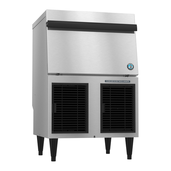
Hoshizaki F-330BAH Service Manual
Self-contained flaker
Hide thumbs
Also See for F-330BAH:
- Service manual (47 pages) ,
- Parts list (23 pages) ,
- Instruction manual (18 pages)

Subscribe to Our Youtube Channel
Related Manuals for Hoshizaki F-330BAH


Summary of Contents for Hoshizaki F-330BAH
- Page 1 Hoshizaki Hoshizaki America, Inc. Self-Contained Flaker Models F-330BAH(-C) SERVICE MANUAL “A Superior Degree of Reliability” www.hoshizaki.com 73151 Number: Issued: 8-2-2007 Revised: 4-22-2013...
- Page 2 Hoshizaki provides this manual primarily to assist qualified service technicians in the service of the appliance. Should the reader have any questions or concerns which have not been satisfactorily addressed, please call, send an e-mail message, or write to the Hoshizaki Technical Support Department for assistance. Phone: 1-800-233-1940; (770) 487-2331 Fax: 1-800-843-1056;...
-
Page 3: Table Of Contents
Important Safety Information ....................5 I. Construction and Water/Refrigeration Circuit Diagram ............7 A. Construction ........................7 1a. F-330BAH(-C) Auxiliary Code C-0 and Earlier ............7 1b. F-330BAH(-C) Auxiliary Code C-1 and Later ............8 B. Ice Making Appliance ....................9 C. - Page 4 2. F-330BAH-C ......................45 C. Wiring Diagrams ......................46 1a. F-330BAH(-C) Label Diagram Auxiliary Code C-0 and Earlier ......46 1b. F-330BAH(-C) Ladder Diagram Auxiliary Code C-0 and Earlier ......47 2a. F-330BAH(-C) Label Diagram Auxiliary Code C-1 and Later ....... 48...
-
Page 5: Important Safety Information
Important Safety Information Throughout this manual, notices appear to bring your attention to situations which could result in death, serious injury, damage to the appliance, or damage to property. WARNING Indicates a hazardous situation which could result in death or serious injury. - Page 6 WARNING, continued • Do not use an extension cord. • Do not use an appliance with a damaged power cord. The power cord should not be altered, jerked, bundled, weighed down, pinched, or tangled. Such actions could result in electric shock or fire. To unplug the appliance, be sure to pull the plug, not the cord, and do not jerk the cord.
-
Page 7: Construction And Water/Refrigeration Circuit Diagram
I. Construction and Water/Refrigeration Circuit Diagram A. Construction 1a. F-330BAH(-C) Auxiliary Code C-0 and Earlier Bin Control The switch actuator is located in the ice storage bin. Ice Storage Bin Control Box Front Spout Inlet Water Valve Evaporator Heater (-C Model) -
Page 8: 1B. F-330Bah(-C) Auxiliary Code C-1 And Later
1b. F-330BAH(-C) Auxiliary Code C-1 and Later Control Box Bin Control The switch actuator is located in the ice storage bin. Ice Storage Bin Front Spout Inlet Water Valve Evaporator Heater (-C Model) Evaporator Reservoir Gear Motor Drain Valve Compressor... -
Page 9: Ice Making Appliance
B. Ice Making Appliance 1. F-330BAH(-C) Cutter Evaporator Heater (-C Model) Extruding Head Upper Bearing Seal Bolt Auger Insulation Cylinder Mechanical-Seal O-Ring Socket Head Cap Screw and Split Lock Washer Housing-Lower Bearing Hex Bolt and Washer Spline Coupling Gear Motor... -
Page 10: Water/Refrigeration Circuit Diagram
C. Water/Refrigeration Circuit Diagram Spout Inlet Water Valve Heater (-C Model) Water Supply Float Switch Water Level Reservoir Evaporator Overflow To Drain Flush/Drain Valve Gear Motor Drier Capillary Tube Fan Motor Condenser High-Pressure Switch Compressor Refrigeration Circuit Water Circuit... -
Page 11: Sequence Of Operation And Service Diagnosis
II. Sequence of Operation and Service Diagnosis A. Sequence of Operation Flow Chart... -
Page 12: Service Diagnosis
B. Service Diagnosis WARNING • The appliance should be diagnosed and repaired only by qualified service personnel to reduce the risk of death, electric shock, serious injury, or fire. • Risk of electric shock. Use extreme caution and exercise safe electrical practices. •... - Page 13 4) Startup/Fill Cycle–Move any ice away from the BC actuator paddle (located at the top of the bin). Move the flush switch to the "ICE" position. X5 relay and WV energize. Reservoir fills, LFS closes, nothing happens at this time. The reservoir continues to fill. X5 Relay Diagnosis: Check that WV energizes and fills the reservoir.
- Page 14 7) Refill/Low-Water Safety Cycle–As ice is produced, water level in the reservoir drops. UFS opens, nothing happens at this time. LFS opens and refill begins. X4 relay de-energizes, low water safety circuit opens (X4 relay #4 (DBU) and #6 (BR), and CB #3 (BR) and #4 (DBU)), CB 90 sec. low-water safety timer starts. WV energizes. Comp, FM, GM, and X3 relay continue.
-
Page 15: 2B. Diagnostic Procedure Auxiliary Code C-1 And Later
2b. Diagnostic Procedure Auxiliary Code C-1 and Later This diagnostic procedure is a sequence check that allows you to diagnose the electrical system and components. Before proceeding, check for correct installation, adequate water supply (minimum of 10 PSIG, maximum of 113 PSIG), and proper voltage per appliance nameplate. - Page 16 5) Ice Purge Cycle–UFS closes, X11 relay energizes, WV de-energizes, and low-water safety circuit (CB #3 and #4) closes. GM and X12 relay energize, 60 sec. Comp delay timer starts. X11 Relay Diagnosis: Check for 35VDC at X11 relay #4 (DBU) to #6 (BR). If 35VDC is present, X11 relay is de-energized or bad.
- Page 17 8) Shutdown–Ice fills ice storage bin and presses BC actuator to open BC. Comp, FM, GM, and X12 relay continue. X10 relay and X11 relay de-energize. 90 sec. low-water safety timer starts. When 90 sec. low-water safety timer terminates, Comp and FM de-energize.
-
Page 18: Control Board Check
C. Control Board Check Before replacing a control board that does not show a visible defect and that you suspect is bad, always conduct the following check procedure. This procedure will help you verify your diagnosis. 1) Startup: Move the power switch to the "OFF" position, then unplug the appliance. Access CB and remove the wires from CB #3, 4, 5, 6, 10, and 11. -
Page 19: Float Switch Check And Cleaning
3) If not already removed, remove the top and rear panels. 4) Remove FS assembly from the reservoir cover. See Fig. 1. 5) Wipe down FS assembly with a mixture of 1 part Hoshizaki "Scale Away" and 25 parts warm water. - Page 20 6) While not necessary, the floats can be removed from the shaft during cleaning. If you remove them, note that the blue float is on top (UFS) and the white float is on bottom (LFS). The floats must be installed with the magnets inside them towards the top of the switch.
-
Page 21: Diagnostic Tables
F. Diagnostic Tables Before consulting the diagnostic charts, check for correct installation, proper voltage per appliance nameplate, and adequate water supply. Check control board using the steps in "II.C. Control Board Check." 1. No Ice Production No Ice Production - Possible Cause Startup 1. - Page 22 No Ice Production - Possible Cause Freeze Cycle 1. Control Board a) Defective. See "II.C. Control Board Check." 2. X3 Relay (C-0 and earlier) or a) Defective. X12 Relay (C-1 and later) 3. Start Relay/Capacitor a) Defective. 4. Compressor a) Open motor windings. b) Mechanical Failure.
-
Page 23: Controls And Relays
III. Controls and Relays The F-330BAH(-C) is controlled by a control board and 5 relays. X1 and X2 relays are located on the control board and control GM, Comp, and FM operation. X10, X11, and X12 relays are independent relays located in the control box. X10 relay controls the icemaking process and DV operation. -
Page 24: Control Board Layout
B. Control Board Layout #10 35VDC #11 35VDC Output Compressor Input Compressor Delay Circuit Delay Circuit #5 and #6 35VDC Jumper • X2 Compressor Relay #3 Compressor #4 115VAC Input #4 35VDC Input Low-Water Safety Circuit #3 35VDC Output Low-Water Safety Circuit #2 Transformer 24VAC Neutral... -
Page 25: Relays
C. Relays X5 (C-0 and earlier) and X10 (C-1 and later)- Control Relay: Relay energizes when power switch is "ON," safety switch closed (if applicable), safety relay (if applicable) de-energized, BC closed, and flush/control switch in "ICE" position. Once energized, relay allows 24VAC to X4 relay (C-0 and earlier) or X11 relay (C-1 and later) for WV initiation and prevents DV from energizing during icemaking process. -
Page 26: Refrigeration Circuit And Component Service Information
IV. Refrigeration Circuit and Component Service Information WARNING • This appliance should be diagnosed and repaired only by qualified service personnel to reduce the risk of death, electric shock, serious injury, or fire. • Move the power switch to the "OFF" position, then unplug the appliance from the electrical outlet before servicing. - Page 27 5) Disconnect the gauge manifold hose from the vacuum pump and attach it to a refrigerant service cylinder. Remember to loosen the connection and purge the air from the hose. For the required refrigerant charge, see the nameplate. Hoshizaki recommends only virgin refrigerant or reclaimed refrigerant which meets ARI Standard...
- Page 28 6) A liquid charge is required when charging an R-404A system (to prevent fractionation). Place the service cylinder on the scales; if the service cylinder is not equipped with a dip tube, invert the service cylinder, then place it on the scales. Open the high-side valve on the gauge manifold.
-
Page 29: Component Service Information
B. Component Service Information NOTICE • When replacing a component listed below, see the notes to help ensure proper operation. • When replacing evaporator assembly and water circuit components, make sure there are no water leaks after the repair is complete. Component Notes Compressor... - Page 30 Spout Assembly C-0 and Earlier Spout (A) Thumbscrew Safety Bracket (A) Spout (A) Spout B Safety Bracket (B) Safety Switch Thumbscrew Spout Assembly C-1 and Later Thumbscrew Spout (A) Spout B Thumbscrew Fig. 3...
- Page 31 Evaporator Assembly Evaporator Heater (-C Model) Flaker Cutter -C Cutter Upper Bearing Upper Bearing (pressed into (pressed into extruding head) extruding head) -C Extruding Head Flaker Extruding Head Auger Packing O Ring Evaporator Flange Seal Bolts Inspect for leakage around seal bolts. Tighten (11.1 ft-lb/15 N·m) or replace as necessary.
-
Page 32: Upper Bearing Wear Check
1. Upper Bearing Wear Check To ensure that the bearing inside the extruding head does not exceed the wear tolerance of .02", follow the instructions below. .02" Round Stock 1) Remove the front panel. Move the power or Pin Gauge switch to the "OFF"... -
Page 33: Removal And Replacement Of Cutter
2. Removal and Replacement of Cutter 1) Remove the front panel. Move the power switch to the "OFF" position, then unplug the appliance from the electrical outlet. 2) Remove the top panel and top insulation panel. 3) Remove the thumbscrews attaching spout (B) to the bin, then remove spout (B). See Fig. -
Page 34: Removal And Replacement Of Auger
4. Removal and Replacement of Auger 1) Remove the front panel, then move the flush/control switch to the "FLUSH" or "DRAIN" position. 2) After 2 min., move the power switch to the "OFF" position, then unplug the appliance from the electrical outlet. 3) Remove the top panel and top insulation panel. -
Page 35: Removal And Replacement Of Evaporator
5. Removal and Replacement of Evaporator IMPORTANT Always install a new drier every time the sealed refrigeration system is opened. Do not replace the drier until after all other repair or replacement has been made. 1) Remove the front panel. Move the flush/control switch to the "FLUSH" or "DRAIN" position. -
Page 36: Removal And Replacement Of Mechanical Seal And Lower Housing
19) Move the flush/control switch to the "ICE" position. Plug the appliance into the electrical outlet, then move the power switch to the "ON" position. 20) Replace the panels in their correct positions. 6. Removal and Replacement of Mechanical Seal and Lower Housing 6a. -
Page 37: Removal And Replacement Of Gear Motor
16) Replace the removed parts in the reverse order of which they were removed. If applicable, make sure the safety switch components are in position. 17) Move the flush/control switch to the "ICE" position. Plug the appliance into the electrical outlet, then move the power switch to the "ON" position. 18) Replace the panels in their correct positions. -
Page 38: Maintenance
V. Maintenance This appliance must be maintained in accordance with the instruction manual and labels provided. Consult with your local Hoshizaki Certified Service Representative about maintenance service. WARNING • Only qualified service technicians should service the appliance. • To reduce the risk of electric shock, do not touch the appliance power switch or flush/control switch with damp hands. -
Page 39: Maintenance Schedule
A. Maintenance Schedule The maintenance schedule below is a guideline. More frequent maintenance may be required depending on water quality, the appliance's environment, and local sanitation regulations. Maintenance Schedule Frequency Area Task Daily Scoop Clean the ice scoop using a neutral cleaner. Rinse thoroughly after cleaning. -
Page 40: Preparing The Appliance For Periods Of Non-Use
VI. Preparing the Appliance for Periods of Non-Use NOTICE When storing the appliance for an extended time or in sub-freezing temperatures, follow the instructions below to prevent damage. When the appliance is not used for two or three days under normal conditions, it is sufficient to move the power switch to the "OFF"... -
Page 41: Disposal
VII. Disposal The appliance contains refrigerant and must be disposed of in accordance with applicable national, state, and local codes and regulations. Refrigerant must be recovered by properly certified service personnel. -
Page 42: Technical Information
VIII. Technical Information A. Specification Sheet 1. F-330BAH AC SUPPLY VOLTAGE 115/60/1 AMPERAGE 6.7A ( AT 104°F/ WT 80°F ) MINIMUM CIRCUIT AMPACITY MAXIMUM FUSE SIZE APPROXIMATE ICE PRODUCTION Ambient WATER TEMP. (°F) PER 24 HR. Temp.(°F) lbs./day (kg/day) * 330(150) -
Page 43: F-330Bah-C
2. F-330BAH-C AC SUPPLY VOLTAGE 115/60/1 AMPERAGE 7.4A (AT 104°F/ WT 80°F) MINIMUM CIRCUIT AMPACITY MAXIMUM FUSE SIZE APPROXIMATE ICE PRODUCTION Ambient WATER TEMP. (°F) PER 24 HR. Temp.(°F) lbs./day (kg/day) * 320(145) 300(136) 290(132) Reference without *marks 275(125) 265(120) -
Page 44: Performance Data Sheet
B. Performance Data Sheet 1. F-330BAH APPROXIMATE Ambient Water Temp. (°F) ICE PRODUCTION Temp. (°F) PER 24 HR. *330 *(150) (143) (136) (132) (127) (123) (116) *250 *(113) (107) lbs./day (kg/day) (104) (100) *205 *(93) APPROXIMATE ELECTRIC *562 CONSUMPTION *606... -
Page 45: F-330Bah-C
2. F-330BAH-C APPROXIMATE Ambient Water Temp. (°F) ICE PRODUCTION Temp. (°F) PER 24 HR. *320 *(145) (136) (132) (125) (120) (114) (109) *230 *(104) (100) lbs./day (kg/day) (95) (91) *190 *(86) *607 APPROXIMATE ELECTRIC CONSUMPTION *650 *665 watts APPROXIMATE WATER... -
Page 46: Wiring Diagrams
C. Wiring Diagrams 1a. F-330BAH(-C) Label Diagram Auxiliary Code C-0 and Earlier *High-Pressure Switch Cut-out 426± PSIG Cut-in 341±22 PSIG... -
Page 47: 1B. F-330Bah(-C) Ladder Diagram Auxiliary Code C-0 And Earlier
1b. F-330BAH(-C) Ladder Diagram Auxiliary Code C-0 and Earlier Auxiliary Code: S-0 Auxiliary Code: S-1 to C-0 *High-Pressure Switch Cut-out 426± PSIG Cut-in 341±22 PSIG... -
Page 48: 2A. F-330Bah(-C) Label Diagram Auxiliary Code C-1 And Later
2a. F-330BAH(-C) Label Diagram Auxiliary Code C-1 and Later *High-Pressure Switch Cut-out 426± PSIG Cut-in 341±22 PSIG... -
Page 49: 2B. F-330Bah(-C) Ladder Diagram Auxiliary Code C-1 And Later
2b. F-330BAH(-C) Ladder Diagram Auxiliary Code C-1 and Later *High-Pressure Switch Cut-out 426± PSIG Cut-in 341±22 PSIG...
Need help?
Do you have a question about the F-330BAH and is the answer not in the manual?
Questions and answers