
Related Manuals for Hoshizaki F-500BAJ


Summary of Contents for Hoshizaki F-500BAJ
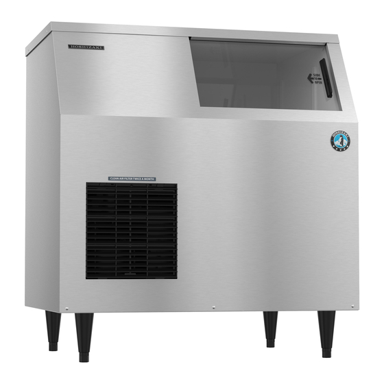
- Page 1 Service Manual Self-Contained Flaker Models F-300BAJ F-500BAJ Number: 73214 hoshizakiamerica.com Issued: 1-30-2017...
- Page 2 Hoshizaki provides this manual primarily to assist qualified service technicians in the service of the appliance. Should the reader have any questions or concerns which have not been satisfactorily addressed, please call, send an e-mail message, or write to the Hoshizaki Technical Support Department for assistance. Phone: 1-800-233-1940; (770) 487-2331 Fax: 1-800-843-1056;...
-
Page 3: Table Of Contents
V. Maintenance ........................47 VI. Disposal .......................... 49 VII. Technical Information ..................... 50 A. Specification & Performance Data Sheets ..............50 1. F-300BAJ ....................... 50 2. F-500BAJ ....................... 51 B. Wiring Diagrams ......................52 1. F-300BAJ ....................... 52 2. F-500BAJ ....................... 53... -
Page 4: Important Safety Information
Important Safety Information Throughout this manual, notices appear to bring your attention to situations which could result in death, serious injury, damage to the appliance, or damage to property. WARNING Indicates a hazardous situation which could result in death or serious injury. - Page 5 WARNING, continued For Corded Models • This appliance is equipped with a NEMA 5-15 three-prong grounding plug reduce the risk of potential shock hazards. Corded models must be plugged into a properly grounded, independent 3-prong wall outlet. If the outlet is a 2-prong outlet, it is your personal responsibility to have a qualified electrician replace it with a properly grounded, independent 3-prong wall outlet.
- Page 6 WARNING, continued • Do not use combustible spray or place volatile or flammable substances near the appliance. They might catch fire. • Keep the area around the appliance clean. Dirt, dust, or insects in the appliance could cause harm to individuals or damage to the appliance. •...
-
Page 7: Construction And Water/Refrigeration Circuit Diagram
I. Construction and Water/Refrigeration Circuit Diagram A. Construction 1. F-300BAJ Bin Control The actuator is located in the ice storage bin. Inlet Water Valve Ice Storage Bin Spout Reservoir Evaporator Gear Motor Control Box Compressor Front... - Page 8 2. F-500BAJ Bin Control The actuator is located Inlet Water Valve in the ice storage bin. Spout Reservoir Ice Storage Bin Evaporator Gear Motor Control Box Compressor Front...
-
Page 9: Icemaking Unit
B. Icemaking Unit 1. F-300BAJ and F-500BAJ Cutter Extruding Head Upper Bearing Seal Bolt Auger Insulation Cylinder Mechanical-Seal O-Ring Socket Head Cap Screw with Split Lock Washer Housing-Lower Bearing Hex Bolt and Washer Spline Coupling Gear Motor... -
Page 10: Water/Refrigeration Circuit Diagram
C. Water/Refrigeration Circuit Diagram Spout Evaporator Condensate Float Inlet Water Valve Drain Pan (Drip Pan) Switch Water Level Water Supply Line Dip Pan Reservoir Drain Hose Evaporator Overflow Hose Thermostatic Expansion Valve Gear Motor Drain Valve Gear Motor Drain Pan Drain Outlet Drier Condenser... -
Page 11: Sequence Of Operation And Service Diagnosis
II. Sequence of Operation and Service Diagnosis A. Sequence of Operation Flow Chart 1. Icemaking and Drain Cycle... -
Page 12: Shutdown
2. Shutdown Control Board Sequence of Operation Flow Chart - Shutdown and Re-Start... -
Page 13: Service Diagnosis
B. Service Diagnosis WARNING • The appliance should be diagnosed and repaired only by qualified service personnel to reduce the risk of death, electric shock, serious injury, or fire. • Risk of electric shock. Use extreme caution and exercise safe electrical practices. •... -
Page 14: Diagnostic Procedure
3) Remove the front panel and move the power switch to the "OFF" position, then unplug the appliance from the electrical outlet (F-300BAJ) or turn off the power supply (F-500BAJ). 4) Remove the control box cover and access CB. 5) Check the CB S1 dip switch settings, see "III.B.1. Default Dip Switch Settings" to assure that they are in the correct positions. - Page 15 6) Startup–CB "POWER OK" LED is on. Plug the appliance into the electrical outlet (F-300BAJ) or turn on the power supply (F-500BAJ), then move the power switch to the "ON" position. Make sure the control switch is in the "ICE" position.
- Page 16 8) Ice Purge Cycle – "GM" LED is on. 5-sec. GM delay timer terminates. GM and CCR energize. Once CCR energizes, 5VDC circuit closes through CCR terminal #3 (W/O) and terminal #5 (W/O) and CB K9 #5 (W/O) and K9 #6 (W/O). After 5VDC circuit closes, 5-min.
- Page 17 10) Refill Cycle – "GM", "COMP", and "WTRIN" LEDs are on. LFS opens. WV energizes and 90-sec. FT starts. Comp, GM, CCR, and FM continue. LFS closes. Nothing occurs at this time. Reservoir continues to fill until UFS closes. When UFS closes, WV de-energizes, 90-sec. FT terminates, and 30-min. FZT starts. If UFS remains open longer than 90 sec.
- Page 18 11) Drain Cycle a) 1-in-1 Drain Cycle: DV energizes once every hour when the 1-in-1 drain cycle is activated (S1 dip switch 4 in the "OFF" position (factory default position)). GM, FM, Comp continue. DV energizes for 2 sec. every hour. This setting is recommended for optimum icemaker performance.
-
Page 19: Control Board Check
C. Control Board Check Before replacing a control board that does not show a visible defect and that you suspect is bad, always conduct the following check procedure. This procedure will help you verify your diagnosis. 1) Check CB S1 dip switch settings to assure that they are in the factory default position. For factory default settings, see "III.B.1. - Page 20 a) Control Switch – CB K9 #1 (W/BK) and CB K9 #2 (W/BK): 5VDC is present between CB white K5 connector, pin closest to CB red K4 connector and CB K9 #1 (W/BK) at all times. If 5VDC is not present, replace CB. When the control switch is in the "ICE"...
- Page 21 5) Fill "WTRIN" LED is on: 24VAC is present at CB K2 #9 (W/R) at all times. If not, confirm 24VAC from CB K2 #9 (W/R) to a neutral (LBU). When LFS open at startup or opens during normal operation, "WTRIN" LED turns on, fill timer (FT) starts, freeze timer (FZT) terminates (only during normal operation), and WV energizes.
- Page 22 "F-C" Control Board • K9 Connector (5VDC) High-Pressure Switch Control Switch #3 to #4 (yellow) (5VDC) #1 to #2 (white/black) (5VDC) Compressor Control Relay Circuit/Gear • "COMP" LED Motor Protect Relay Circuit (X1 Relay) #5 to #6 (white/orange) (5VDC) Comp •...
-
Page 23: Bin Control Check
1) Remove the front panel and move the power switch to the "OFF" position, then unplug the appliance from the electrical outlet (F-300BAJ) or turn the power supply off (F-500BAJ). 2) Disconnect the 12 pin connector from the control box or disconnect the bell connectors. - Page 24 7) Remove the control box cover, then plug the appliance into the electrical outlet (F-300BAJ) or turn on the power supply (F-500BAJ). Next, confirm the control switch is in the "ICE" position, then move the power switch to the "ON" position.
-
Page 25: Float Switch Check And Cleaning
6) Plug the appliance back into the electrical outlet (F-300BAJ) or turn on the power supply (F-500BAJ). Next, move the control switch to the "ICE" position, then move the power switch to the "ON" position and let the water reservoir fill. - Page 26 (F-300BAJ) or turn off the power supply (F-500BAJ). 3) Remove the float switch assembly from the reservoir cover. See Fig. 4. 4) Wipe down FS assembly with a mixture of 1 part Hoshizaki "Scale Away" and 25 parts warm water.
-
Page 27: Diagnostic Tables
F. Diagnostic Tables Before consulting the diagnostic charts, check for correct installation, proper voltage per appliance nameplate, and adequate water supply. Check control board using the steps in "II.C. Control Board Check." 1. No Ice Production No Ice Production - Possible Cause Startup 1. - Page 28 No Ice Production - Possible Cause Freeze Cycle 1. Control Board a) Defective. See "II.C. Control Board Check." 2. Start Relay/Capacitor a) Defective. 3. Compressor a) Open motor windings. b) Mechanical Failure. 4. Fan Motor a) Open motor windings. b) Mechanical failure or fan blade binding. 5.
-
Page 29: Controls And Adjustments
III. Controls and Adjustments A. Control Board • A Hoshizaki exclusive control board is employed. • All models are pretested and factory adjusted. • For a control board check procedure, see "II.C. Control Board Check." NOTICE • Fragile, handle very carefully. - Page 30 1. "F-C" Control Board Layout • K9 Connector (5VDC) High-Pressure Switch Control Switch #3 to #4 (yellow) (5VDC) #1 to #2 (white/black) (5VDC) Compressor Control Relay Circuit/Gear • "COMP" LED Motor Protect Relay Circuit (X1 Relay) #5 to #6 (white/orange) (5VDC) Comp •...
- Page 31 2. LED Lights and Audible Alarm Safeties The "POWER OK" LED indicates proper control voltage and will remain on unless a control voltage problem occurs. For further details, see "II.A. Sequence of Operation Flow Chart." Energized Sequence Step Components Min. Max.
-
Page 32: Controls And Adjustments
Dip switches are factory set. Failure to maintain factory settings may adversely affect performance and warranty coverage. For more information, contact your Hoshizaki Certified Service Representative. 1. Default Dip Switch Settings The S1 dip switch settings are factory-set to the following positions: Dip Switch No. -
Page 33: Infrared Sensor Shutdown Delay (S1 Dip Switch 1, 2, 3)
For a typical dispenser unit application, a 100-sec. shutdown delay is recommended. When used with a standard Hoshizaki ice storage bin, any shutdown delay setting is acceptable. WARNING! Increasing the shutdown delay allows a higher level of ice in the dispenser unit/ice storage bin before shutdown. -
Page 34: Bin Control Selector (S1 Dip Switch 7)
5. Bin Control Selector (S1 dip switch 7) The bin control selector is factory set. Do not adjust. When used on a standard ice storage bin, only the mechanical bin control should be used. When the mechanical bin control is used (S1 dip switch 7 in the off position), the gear motor delay after the upper float switch closes is 5 sec. -
Page 35: Power Switch And Control Switch
C. Power Switch and Control Switch The power switch and the control switch are used to control the icemaker. They are located on the control box. 1. Power Switch The power switch has 2 positions, "OFF" and "ON." When the power switch is in the "OFF"... -
Page 36: Refrigeration Circuit And Component Service Information
IV. Refrigeration Circuit and Component Service Information WARNING • This appliance should be diagnosed and repaired only by qualified service personnel to reduce the risk of death, electric shock, serious injury, or fire. • Move the power switch to the "OFF" position and turn off the power supply. Place the disconnect in the "OFF"... - Page 37 5) Disconnect the gauge manifold hose from the vacuum pump and attach it to a refrigerant service cylinder. Remember to loosen the connection and purge the air from the hose. For the required refrigerant charge, see the nameplate. Hoshizaki recommends only virgin refrigerant or reclaimed refrigerant which meets ARI Standard...
- Page 38 6) A liquid charge is required when charging an R-404A system (to prevent fractionation). Place the service cylinder on the scales; if the service cylinder is not equipped with a dip tube, invert the service cylinder, then place it on the scales. Open the high-side valve on the gauge manifold.
-
Page 39: Component Service Information
If new seal bolts do not have preapplied threadlocker, apply Loctite 243 or equivalent threadlocker to seal bolt threads. Tighten to the torque value listed below. Torque for F-300BAJ and F-500BAJ: 11.1 ft-lb/15 N·m. Tighten 2 times. Allow at least 5 sec. in between each tightening. Component... - Page 40 Evaporator Assembly Flaker Cutter Upper Bearing (pressed into extruding head) Flaker Extruding Head Auger O Ring Evaporator Flange Packing Seal Bolts Inspect for leakage around seal bolts. Tighten (11.1 ft-lb/15 N·m) or replace as necessary. Seal bolts must be replaced once removed because seal material is one-time use only.
- Page 41 2. Removal and Replacement of Cutter 1) Remove the front panel. Move the power switch to the "OFF" position, then unplug the appliance from the electrical outlet (F-300BAJ) or turn off the power supply (F-500BAJ). 2) Remove the top and side panels.
- Page 42 Loctite 243 or equivalent threadlocker to seal bolt threads. • Torque for F-300BAJ and F-500BAJ: 11.1 ft-lb/15 N·m. Tighten 2 times. Allow at least 5 sec. in between each tightening. 3. Removal and Replacement of Extruding Head 1) Drain the water from the evaporator.
- Page 43 Move the power switch to the "OFF" position, then unplug the appliance from the electrical outlet (F-300BAJ) or turn off the power supply (F-500BAJ). 2) Remove the top and side panels. 3) Recover the refrigerant and store it in an approved container.
- Page 44 16) Evacuate the system, and charge it with refrigerant. For air-cooled and water-cooled models, see the nameplate for the required refrigerant charge. For remote models, see the rating label inside the icemaker. Hoshizaki recommends only virgin refrigerant or reclaimed refrigerant which meets AHRI Standard 700 (latest edition) be used.
- Page 45 Move the power switch to the "OFF" position, then unplug the appliance from the electrical outlet (F-300BAJ) or turn off the power supply (F-500BAJ). 2) Remove the top and side panels. 3) Remove the strap connecting the spout to the chute assembly, then remove the spout.
- Page 46 Move the power switch to the "OFF" position,then unplug the appliance from the electrical outlet (F-300BAJ) or turn off the power supply (F-500BAJ). 2) Remove the top and side panels. 3) Remove the strap connecting the spout to the chute assembly, then remove the spout.
-
Page 47: Maintenance
V. Maintenance The appliance must be maintained in accordance with the instruction manual and labels provided. Consult with your local Hoshizaki Certified Service Representative about maintenance service. WARNING • Only qualified service technicians should service the appliance. • To reduce the risk of electric shock, do not touch the icemaker power switch or control switch with damp hands. - Page 48 If new seal bolts do not have preapplied threadlocker, apply Loctite 243 or equivalent threadlocker to seal bolt threads. • Torque for F-300BAJ and F-500BAJ: 11.1 ft-lb/15 N·m. Tighten 2 times. Allow at least 5 sec. in between each tightening. Yearly Inlet Water Valve Close the water supply line shut-off valve and drain the water system.
-
Page 49: Disposal
VI. Disposal The appliance contains refrigerant and must be disposed of in accordance with applicable national, state, and local codes and regulations. Refrigerant must be recovered by properly certified service personnel. -
Page 50: Technical Information
VII. Technical Information We reserve the right to make changes in specifications and design without prior notice. A. Specification & Performance Data Sheets Note: The data in bold should be used for reference. 1. F-300BAJ Specification Sheet AC SUPPLY VOLTAGE 115/60/1 AMPERES 7.8 AMPS (AT 104°F / WT 80°F) -
Page 51: F-500Baj
2. F-500BAJ Specification Sheet AC SUPPLY VOLTAGE 115/60/1 COMPRESSOR 115/60/1 10.5 RLA 54.5 LRA GEAR MOTOR 115 V 2.4 FLA 1/4 HP FAN MOTOR 115 V 0.85A MAX OTHER 115 V 0.03 A MAXIMUM FUSE SIZE 20 A MAX. HACR BREAKER (USA ONLY) 20 A MAX. -
Page 52: Wiring Diagrams
B. Wiring Diagrams 1. F-300BAJ *High-Pressure Switch Cut-out 426± PSIG Cut-in 341±22 PSIG... -
Page 53: F-500Baj
2. F-500BAJ *High-Pressure Switch Cut-out 426± PSIG Cut-in 341±22 PSIG...
Need help?
Do you have a question about the F-500BAJ and is the answer not in the manual?
Questions and answers