Table of Contents

Related Manuals for ExpertDAQ EX9212LoRa Series


Summary of Contents for ExpertDAQ EX9212LoRa Series
- Page 1 EX9212LoRa series User Manual LoRa Interface Converter & DI/DO Controller EX9212LoRa-E/MTCP EX9212LoRa-S EX9212LoRa-U EX9212LoRa-DIO User Manual Edition: 201909v1.1 • Manual Version 1.1.0 • 2019-09-19 www.topsccc.com EX9212LoRa Series...
-
Page 2: Table Of Contents
EX9212LoRa series User Manual Table of Contents Table Of Contents…………………………………………………………………………………………………………………………………….2 1. Introduction………………………………………………………………………………………………………………………………………..3 1.1 Applications…………………………………………………………………………………………………………………………………. 4 1.2 Packaging………………………………………………………………………………………………………………………………………4 2. Product Specifications……………………………………………………………………………………………………..…………………..5 2.1 EX9212LoRa-E/Mtcp : Ethernet To LoRa…………………………………………………………………………………………5 2.2 Ex9212 LoRa -S : Rs-232(Half-Duplex)/485 To Lora………………………………………………………………………...6 2.3 Ex9212 LoRa -U : Usb To Lora…………………………………………………………………………………………………………7 2.4 Ex9212 LoRa -Dio : LoRa Digital I/O Controller……………………………………………………………………………..8... -
Page 3: Introduction
EX9212LoRa series User Manual 1. Introduction Thank you for using LoRa interface gateway in your system work. These LoRa gateways provide the way of connecting IoT remote units to a Local Area Network (LAN) or Host Computer from long distance. The data transmission via LoRa gateways mainly intended for the ISM (Industrial, Scientific, and Medical) frequency bands at 862-936 MHz. -
Page 4: Applications
EX9212LoRa series User Manual 1.1 Applications ● Automation and safety alarm in the community. ● Various automated smart meters, such as water meter, gas meter and electricity meter. ● Long range communication data collection and integration. ● Outdoor information monitoring and collection, such as temperature, humidity and air quality information. -
Page 5: Product Specifications
EX9212LoRa series User Manual 2. Product Specifications 2.1 EX9212LoRa-E/ MTCP : Ethernet To LoRa CPU : 32 bits MCU ,40 MHz , 16KB SRAM, 128KB Flash ROM Support: ModbusTCP(EX9212LoRa-MTCP) & Transparent(EX9212LoRa-E) LoRa : Semtech SX1272 ● Freq. : ISM band 862 ~ 936MHz ●... -
Page 6: Ex9212Lora-S : Rs232(Half-Duplex)/485 To Lora
EX9212LoRa series User Manual 2.2 EX9212LoRa-S : RS232(half-duplex)/485 To LoRa CPU : 32 bits MCU ,40 MHz , 16KB SRAM, 128KB Flash ROM Support: Modbus & Transparent LoRa : Semtech SX1272 Freq. : ISM band 862 ~ 936MHz ... -
Page 7: Ex9212Lora-U : Usb To Lora
EX9212LoRa series User Manual 2.3 EX9212LoRa-U : USB To LoRa CPU : 32 bits MCU ,40 MHz , 16KB SRAM, 128KB Flash ROM Support: only transparent LoRa : Semtech SX1272 ● Freq. : ISM band 862 ~ 936MHz ●... -
Page 8: Ex9212Lora-Dio : Lora Digital I/O Controller
EX9212LoRa series User Manual 2.4 EX9212LoRa-DIO : LoRa Digital I/O Controller CPU : 32 bits MCU ,40 MHz , 16KB SRAM, 128KB Flash ROM Support Modbus Protocol LoRa : Semtech SX1272 Freq. : ISM band 862 ~ 936MHz ... -
Page 9: Product Views
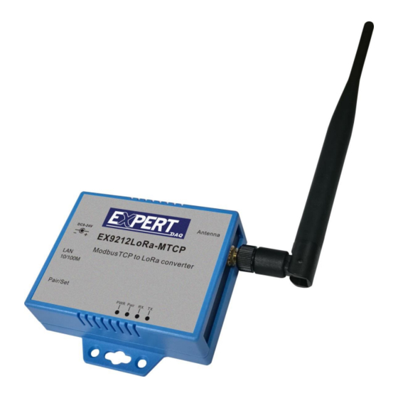
EX9212LoRa series User Manual 3. Product Views 3.1 EX9212LoRa-E/MTCP : Ethernet To LoRa Antenna DC-IN Power Outlet Ethernet LAN port Reset button LED Indicators 3.2 EX9212LoRa-S : RS-485 To LoRa DC-IN Power Outlet Antenna RS-485 Reset button RS-232(half-duplex) LED Indicators 3.3 EX9212LoRa-U : USB To LoRa... -
Page 10: Ex9212Lora-Dio : Lora To Digital I/O Controller
EX9212LoRa series User Manual Antenna Reset button USB port LED Indicators 3.4 EX9212LoRa-DIO : LoRa to Digital I/O Controller Antenna DC-IN Power Outlet Reset button LED Indicators 2 DI / 2 DO port 3.5 Outlined Components • Manual Version 1.1.0 •... -
Page 11: Led Indicators
EX9212LoRa series User Manual 3.5.1 DC-IN Power Outlet LoRa Gateways are powered by a 9~24V DC (Inner positive, outer negative) power supply and 1.0A current. Connecting the AC plug to the AC power socket and put the DC Jack plug into the outlet of device. -
Page 12: Wiring Architecture
EX9212LoRa series User Manual 4. Wiring Architecture 4.1 Ethernet + LoRa --- air ---- LoRa + Serial Interface ----- Machine 4.2 USB Interface + LoRa --- air ---- LoRa + Serial Interface ---- Machine 4.3 Ethernet + LoRa --- air ---- LoRa + Serial DI/DO Interface ----- DI/DO •... - Page 13 EX9212LoRa series User Manual 4.4 Serial Interface + LoRa --- air ---- LoRa + Serial Interface ----- Machine 4.5 Star topology • Manual Version 1.1.0 • 2019-09-19 www.topsccc.com EX9212LoRa Series...
-
Page 14: Lora Module Setting Utility
EX9212LoRa series User Manual 5. LoRa module Setting Utility 5.1 LoRa Setting Tool factory default Uart Baud Rate [bps] 9600 Parity None Date Bit Stop Bit LoRa Frequency [Hz] 915500000 Spreading Factor Bandwidth [kHz] Tx Power [dBm] Encryption 30313233343536373839414243444546 Spreading Factory (for reference only, not exactly to real device): •... -
Page 15: Dip Switch At Top Of Casing
EX9212LoRa series User Manual 5.2 Dip Switch at top of casing: 1) Setting mode: #1~#4 pins all at up position to modify LoRa settings. 2) Operation mode: only #1 at down position to run data transmission. 6. LoRa setting process 6.1 Pull power off:... - Page 16 EX9212LoRa series User Manual 6.6 Setting UART parameters 6.7 Setting LoRa parameters 6.8 Function Pass Mode and Device ID: (pended) 6.9 Encryption value should be same on paring devices. Encryption is optional for security purpose. 6.10 Interface: (pended) 6.11 Press “Write” button to write parameters back to device.
-
Page 17: Ethernet To Lora Settings
EX9212LoRa series User Manual 7. Ethernet to LoRa settings 7.1 Installation of IP Search Tool 7.1.1 Find out “EXBrowser.EXE” in the CD ROM, copy the file to your host computer. 7.1.2 Double click to run “EXBrowser.EXE”, a window will pop up as below. -
Page 18: Web Configuration
EX9212LoRa series User Manual 7.2.7 Click on the icon of “Modify IP”. Input IP and click “Confirm” twice. No need to input password. Web configuration: Input Converter’s IP to Web browser. Configuration pate will show up. Click “Login” without password. -
Page 19: Serial Port Setting
EX9212LoRa series User Manual setting(Please don’t change the parameters inside the red square.) Serial port EX9212LoRa-MTCP: Only use port #1 with default socket 501, Port #2 is not used. EX9212LoRa-E: Press “Update” to save new parameters and reboot. • Manual Version 1.1.0 •... -
Page 20: Serial Interface To Lora Setting
EX9212LoRa series User Manual 8. Serial Interface to LoRa setting Just follow above LoRa setting procedure. 9. USB to LoRa setting Just follow above LoRa setting procedure. 10.LoRa to DI/DO setting: Modbus codes 10.1 Digital Output port #1 10.1.1 port #1 ON : 01 06 00 00 00 01 10.1.2 port #1 OFF: 01 06 00 00 00 00... - Page 21 EX9212LoRa series User Manual Appendix A Pin Assignment DC Power outlet RS-232 Pin Assignment (half-duplex) The pin assignment scheme for a 9-pin male connector on a DTE is given below. PIN 1 : DCD PIN 2 : RXD PIN 3 : TXD...
Need help?
Do you have a question about the EX9212LoRa Series and is the answer not in the manual?
Questions and answers