
Subscribe to Our Youtube Channel
Related Manuals for Fluke TS 90


Summary of Contents for Fluke TS 90
- Page 1 Cable Fault Finder Users Guide PN 2448335 October 2005, Rev. 2 9/2015 ©2005, 2009, 2015 Fluke Corporation All product names are trademarks of their respective companies.
- Page 2 LIMITED WARRANTY AND LIMITATION OF LIABILITY Each Fluke Networks product is warranted to be free from defects in material and workmanship under normal use and service unless stated otherwise herein. The warranty period for the mainframe is 18 months and begins on the date of purchase. Parts, accessories, product repairs and services are warranted for 90 days, unless otherwise stated.
-
Page 3: Table Of Contents
Contents Title Page Introduction ..............1 Registration ..............1 Contacting Fluke Networks ..........1 Safety Information ............2 Design Features ...............3 Physical Characteristics ...........4 Line Cords and Accessories ..........5 Operation ................5 Installing Batteries ...........6 Turning on the Tester ..........7 Automatic Power-Down ..........7 Testing Cables ............7 SmartTone™... - Page 4 TS90 Cable Fault Finder Users Guide...
-
Page 5: Introduction
Registering your product with Fluke Networks gives you access to valuable information on product updates, troubleshooting tips, and other support services. To register, fill out the online registration form on the Fluke Networks website at www.flukenetworks.com/registration. Contacting Fluke Networks www.flukenetworks.com support@flukenetworks.com... -
Page 6: Safety Information
TS90 Cable Fault Finder Users Guide Safety Information The following IEC symbols are used either on the tester or in the manual: Warning: Risk of personal injury. See the manual for details. Caution: Risk of damage or destruction to equipment or software. See the manual for details. -
Page 7: Design Features
Design Features Design Features Design features of the TS90 Cable Fault Finder include: Easy to use Tests all common cable pairs Provides low cost protection against lost time due to cable and connector problems Single button operation ... -
Page 8: Physical Characteristics
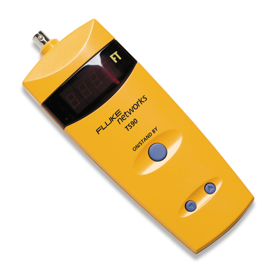
TS90 Cable Fault Finder Users Guide Physical Characteristics See Figure 1. cab01.eps Figure 1. Physical Characteristics Power button, which turns the tester on and off. Low battery LED. Female BNC (British Naval Connector). LCD display with units indication (feet). ... -
Page 9: Line Cords And Accessories
VOP up or down. See “Velocity of Propagation” on page 10. Line Cords and Accessories Use only line cords (test leads) approved by Fluke Networks. Other cords may cause incorrect measurements. For information on availability of additional line cords and accessories, contact your local Fluke Networks authorized distributor. -
Page 10: Installing Batteries
NEVER directly by the conductive wire. Use only the insulated clips provided to connect to any wire or cable. Caution Use only line cords approved by Fluke Networks. Other cords may cause incorrect measurements. Legal requirements may exist regarding... -
Page 11: Turning On The Tester
Operation Turning on the Tester Turn the tester on by pressing the ON/STANDBY button. The tester performs a self test each time it is turned on. During the self test, the tester displays 8.8.8.8. Automatic Power-Down To save battery power, the tester automatically turns off after five minutes if it is not connected to anything, or one hour after you connect to a cable. -
Page 12: Smarttone™ Positive Identification System
TS90 Cable Fault Finder Users Guide Table 1. Display and Beeper Indications Condition Display Beeper Open cable LLLL Shorted cable LLLL Continuous On Cable is too long to –Err Staggered measure A dc load (light bulb, TV, –Err Staggered etc.) is detected >15 Vac is detected 8888 Rapid... - Page 13 Operation To use the SmartTone System: Connect the tester to a wire pair; then turn on the tester. At the other end of the cable, use your tone probe to find the wire pair by probing for the pair with the loudest tone.
-
Page 14: Velocity Of Propagation (Vop)
TS90 Cable Fault Finder Users Guide Velocity of Propagation (VOP) VOP is a cable specification indicating the speed at which a signal travels down the cable. A VOP of 66 means the signal travels at 66 % of the speed of light. The tester uses VOP to calculate cable length. - Page 15 Operation To determine the VOP of a known length of cable: Connect a known length of cable to the tester. The cable must be 200 feet (60 meters) or longer (such as an unopened box of wire). Turn the tester on while holding down the UP or DOWN button.
-
Page 16: Applications
TS90 Cable Fault Finder Users Guide Applications See Figure 3. The tester locates opens, short circuits, and crosses in any two metallic conductors (twisted, untwisted, coax, copper, aluminum, and steel). It identifies conductors using the SmartTone feature and an inductive probe (not included) (see Figure 2). Tone can be sent between two technicians to ID multiple pairs. - Page 17 Applications cab03.eps Figure 3. Testing for Lengths, Shorts, Opens, and Terminations...
-
Page 18: Testing Wire In Conduit
TS90 Cable Fault Finder Users Guide Testing Wire in Conduit There are two methods for testing wire in conduit. You can test a wire pair or a single wire. Testing a Wire Pair in a Conduit To test a wire pair, connect the two test leads to the pair. If one wire separates from the other for 1 ft or more, the tester indicates an open at the separation. - Page 19 Applications At the job-site, you can determine if the cable remaining on your spool or in your box will be sufficient for the job at hand. This will save you an unnecessary trip to the warehouse for more cable, and help you avoid running out of cable in the middle of an installation.
- Page 20 TS90 Cable Fault Finder Users Guide Table 2. Values and Maximum Length for Specifically Identified Cables Maximum Length (Feet) Cable 2000 Lucent 1024 006ABE 6/24 W1000, 6 pair CAT3 (Blue-White) 1500 BICC General Aerial Service Wire (ASW) 2/22, 2 Pair Drop Wire 2000 Superior Essex, 4 pair CAT3...
- Page 21 Applications Table 2. Values and Maximum Length for Specifically Identified Cables (continued) Maximum Length (Feet) Cable Belden 88760 2 wire shielded 18 AWG, Red-Black Belden 88760 2 wire shielded 18 AWG, Red/Black-Shield Carol C1156 RG-174/U BICC General, E22025, Red-Black 1000 Channel Master Polyclad Model 9354 300 Ohm Foam Antenna Wire...
- Page 22 TS90 Cable Fault Finder Users Guide Table 3. VOP Values for Other Cables Cable Type Belden Drop Foam CommScope Drop CommScope Trunk RG58/U 50 Ohm Network Coax RG59 TV Coax Service Wire Times Fiber Drop Times Fiber Dynafoam Times Fiber Trunk Trilogy Trunk Twisted Pair, Gel Filled 19 AWG Twisted Pair, Gel Filled 22 AWG...
-
Page 23: In Case Of Unstable Or Unusual Readings
Time Domain Reflectometry (TDR) Technology In Case of Unstable or Unusual Readings Sometimes, devices connected to the cable you are testing can prevent the TS90 from making a valid reading. Such devices include telephones, fax machines, modems, speakers, transformers, light bulbs, televisions, and dc loads. The software makes the best decisions it can when faced with unusual conditions, but may not always be able to ignore connected devices. - Page 24 TS90 Cable Fault Finder Users Guide For example, if one or both wires of the pair are broken (open), or they are shorted to each other, or they become sufficiently separated from each other, their impedance will change. The tester looks for these changes in impedance. If the impedance change is large enough, (e.g., such as that caused by a break in one of the wires of the pair), the tester will detect the impedance change and will display the length...
- Page 25 Time Domain Reflectometry (TDR) Technology TDR technology examines this TDR waveform (see Figure 4), looking at the sizes of the flat sections and the bumps. The software decides which of the elements of the waveform is most representative of the common problems encountered in the wiring industries and reports the distance to that element.
-
Page 26: Vop Variations
TS90 Cable Fault Finder Users Guide The actual formula used is as follows: Time in billionths of a second --------------------------------------------------------------------------------- - ----------------- - Length 0.9835 The time is divided by two because the signal traveled the length of the cable twice. Once when it left the tester and went to the failure point, and again when it reflected back to the tester to be detected. -
Page 27: Maximum Length
Time Domain Reflectometry (TDR) Technology Depending on the cable construction (shielded, twisted, etc.), insulating material (foam, air, fiber, etc.), and conductors tested (wire-to-wire, wire-to-shield), coiling the cable on a spool or in a box may alter its VOP. Additionally, other conductors in close proximity to the conductors being tested can affect the VOP. -
Page 28: Frequently Asked Questions
TS90 Cable Fault Finder Users Guide Frequently Asked Questions Q: How do I calibrate the tester or perform a self test? A: There are no adjustments inside the tester, and the internal coating protects the critical components from moisture and contaminants. There is nothing to calibrate. A self test is performed by the tester every time you turn it on. - Page 29 Frequently Asked Questions A: No. The accuracy of the reading is dependent on the setting of the VOP. While the nominal setting for general testing is -66-, the VOP for that kind of cable is -56-. To improve the accuracy of length measurements for that or any cable, change the VOP as shown in the instructions in the Velocity of Propagation section.
- Page 30 TS90 Cable Fault Finder Users Guide Q: I accidentally cracked the plastic housing, does this affect the moisture protection of the components? A: Not at all. The component protection is provided by a coating on the components and Printed Circuit Board (PCB). However, if sufficient plastic is missing then a possible shock hazard exists.
- Page 31 Frequently Asked Questions Q: When testing a set of wires that go into a conduit, I sometimes get a reading of 0 or 1. Why? A: If there is more than a foot or so of wires that are physically separated before they enter the close confinement of the conduit, this will look to the tester like an open at the start of the cable.
-
Page 32: If Something Seems Wrong With The Tester
TS90 Cable Fault Finder Users Guide If Something Seems Wrong with the Tester The display remains at 8.8.8.8. after power on. The self test has failed. The batteries may be weak or the tester has water inside. Try changing the batteries or drying the tester. -
Page 33: Maintenance
Maintenance Maintenance Warning These servicing instructions are for use by qualified personnel only. To avoid electric shock, do not perform any servicing other than that contained in the operating instructions unless you are qualified to do so. Disconnect clips from any metallic connections before performing any maintenance. -
Page 34: Specifications
TS90 Cable Fault Finder Users Guide Specifications Power 4 AA alkaline batteries, provide 50 hours of operation Reverse No damage to the tester will occur if the Battery batteries are installed backwards. Protection Input 250 V rms ac, continuous with transient Protection <1500 Vpk Moisture... - Page 35 Specifications Specifications (continued) Length ±2 feet for cables less than 10 feet Accuracy ±5 feet for cables longer than 10 feet and shorter than 200 feet ±3 % and ±5 feet for cables longer than 200 feet An ac voltage of more than High Voltage Detection 5 V rms will trigger the High Voltage...
- Page 36 TS90 Cable Fault Finder Users Guide Specifications (continued) Temperature Range Operating 32 °F to 131 °F (0 °C to 55 °C) Storage -40 °F to 158 °F (-40 °C to 70 °C) Humidity Operating 0 % to 80 % Storage 0 % to 100 % Weight...
Need help?
Do you have a question about the TS 90 and is the answer not in the manual?
Questions and answers