
Related Manuals for RKI Instruments GD-K7D2


Summary of Contents for RKI Instruments GD-K7D2
- Page 1 Model GD-K7D2 (24 VDC) Sample Draw Detector Operator’s Manual Part Number: 71-0078RK Revision: 0 Released: November 18, 2002 RKI Instruments, Inc. • 33248 Central Ave. • Union City, CA 94587 • (510) 441-5656...
- Page 2 Product Warranty RKI Instruments, Inc. warrants gas alarm equipment sold by us to be free from defects in materials, workmanship, and performance for a period of one year* from the date of shipment from RKI Instruments, Inc. Any parts found defective within that period will be repaired or replaced, at our option, free of charge.
-
Page 3: Table Of Contents
Connecting Sample Lines to the GD-K7D2........ -
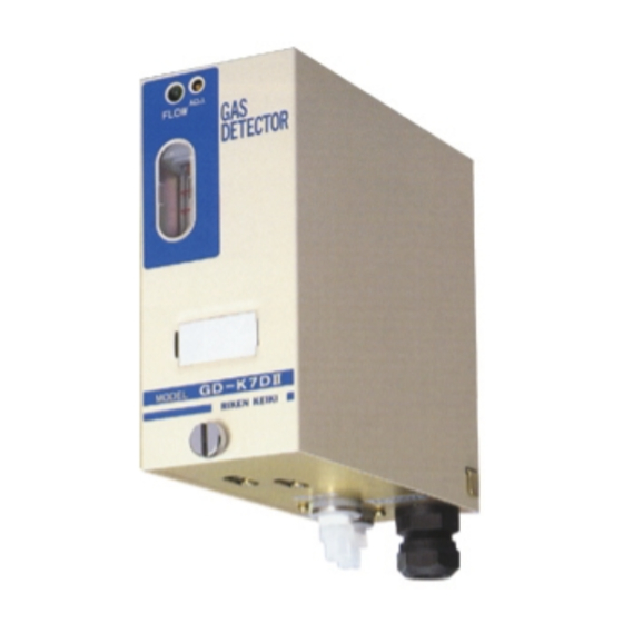
Page 4: Overview
Overview This manual describes the 24 VDC version of the Model GD-K7D2 sample draw 4 - 20 mA transmitter detector head. This manual also describes how to install, start up, maintain, and calibrate the GD-K7D2 when it is used with a gas monitoring controller. A parts list at the end of this manual lists replacement parts and accessories for the GD-K7D2. -
Page 5: Description
(RF)- and dust-resistant. A thumbscrew on the front of the cover near the bottom secures the cover to the installation bracket (see Figure 1). The cover includes a label on the front that indicates the target gas and detection range of the GD-K7D2. Model GD-K7D2 (24 VDC) Sample Draw Transmitter • 5... -
Page 6: Detection Unit
Zero Pot Gain Pot (Factory Adjust) Factory Adjust Pot TP1 (+) Output TP2 (+) Sample Adapter Sensor Retaining Clamp Pump Bracket Pump Captive Retaining Screw Figure 3: Detection Unit Component Location 6 • Model GD-K7D2 (24 VDC) Sample Draw Transmitter... - Page 7 The flow light is at the top left corner of the detection unit (see Figure 2 and 3). The green flow light is on when the GD-K7D2’s flow rate is at an acceptable flow rate. If the flow rate drops below or rises above the acceptable flow rate, the flow light turns off.
-
Page 8: Installation Bracket
Lithium Battery Pack A 3.6 volt lithium battery pack is above the pump on the right side of the GD-K7D2. The lithium battery pack maintains a bias voltage on the gas sensor when the GD-K7D2 is not receiving incoming power, such as during shipment or storage. If the GD-K7D2 is off power for an extended period and the lithium battery pack is dead, the gas sensor operation will be affected when the GD-K7D2 is started up. - Page 9 This jumper is installed when the GD-K7D2 is used with a controller that does not have a flow alarm circuit and flow alarm terminals for wiring to the GD-K7D2. It is not installed when the GD-K7D2 is used with a controller that has flow alarm circuitry and flow alarm terminals.
-
Page 10: Installation
Select a site that is easily accessible for servicing. • Select a site where the GD-K7D2 is not likely to be bumped or disturbed. Make sure there is sufficient room to make wiring and sample line connections at the bottom of the GD-K7D2. Also make sure there is sufficient room to perform start-up, maintenance, and calibration procedures. -
Page 11: Connecting Sample Lines To The Gd-K7D2
Install a short piece, up to 20 cm long, of 4 mm I.D. x 6 O.D. mm Teflon PTFE sample tubing to the gas in fitting as shown in Figure 6 below. Model GD-K7D2 (24 VDC) Sample Draw Transmitter • 11... - Page 12 Be sure not to exceed the maximum sample tubing length listed in Table 2. 20 cm Max Sample In Fitting Sample Filter To Sample Area Figure 7: Installing the Sample Filter 12 • Model GD-K7D2 (24 VDC) Sample Draw Transmitter...
-
Page 13: Wiring The Gd-K7D2
Guide a three or six conductor shielded cable through the cable bushing at the bottom of the GD-K7D2 installation unit. A three conductor cable is used when the GD-K7D2 is wired to a controller that does not have flow alarm circuitry and flow alarm terminals for connection to the GD- K7D2 (see Figure 8 below). - Page 14 Terminal Strip Factory Installed Jumper Cable Shield Controller, Typical 4 - 20 mA In (FB) (DC Ground) + 24 VDC Figure 8: Wiring the GD-K7D2 to a Controller Without Flow Alarm Terminals 4-20 mA DC24V FLOW External Wiring ALARM Terminal Strip...
-
Page 15: Assembling The Gd-K7D2
flowmeter, the incoming sample line is not leaking. CAUTION: Allow the GD-K7D2 to warm up for 30 minutes (2 hours for ammonia units) before you continue with the next section. If the lithium battery pack is dead and the GD- K7D2 has been off power for an extended period of time, allow the GD-K7D2 to warm up overnight. -
Page 16: Operation
flow. Low Flow Alarm If the GD-K7D2’s flow rate drops low enough so that the flow ball is at the bottom of the flowmeter, the GD-K7D2 will go into low flow alarm after a delay of about one minute. -
Page 17: Maintenance
GD-K7D2. It includes daily, monthly, and quarterly procedures. Daily Verify that the flow light on the front of the GD-K7D2 is on. If it is off, see the Troubleshooting section below. Verify that the flowmeter ball is between the two lines on the flowmeter. If necessary, use the flow rate potentiometer to adjust the flow rate, so the flowmeter ball is... -
Page 18: Troubleshooting
The GD-K7D2 wiring to the controller is disconnected or misconnected. • The24 VDC to the GD-K7D2 is interrupted. • The GD-K7D2’s flow rate is too low because of an obstructed sample line, failed pump, etc. 18 • Model GD-K7D2 (24 VDC) Sample Draw Transmitter... - Page 19 At the GD-K7D2, set the correct flow rate with flow rate potentiometer. If you cannot set the correct flow rate, check the sample lines for obstructions or kinks. Verify that the GD-K7D2 wiring is correct and secure. The Installation section of this manual describes GD-K7D2 wiring connections.
-
Page 20: Storing The Gd-K7D2
Storing the GD-K7D2 The GD-K7D2 has a circuit on the main board that keeps a bias voltage on the gas sensor whenever there is no incoming power, such as during shipment, storage, or power outages. This circuit is powered by the lithium battery pack. If the lithium battery pack is dead when power to the GD-K7D2 is turned off or is lost, then the bias voltage normally on the sensor during operation will not be applied to the sensor. - Page 21 17. Reinstall the GD-K7D2 cover. 18. Turn on power to the controller and turn on the controller. 19. If providing 24 VDC to the GD-K7D2 from a source other than the controller, turn on the power source. 20. Place the ON/OFF switch in the ON position.
- Page 22 14. Reinstall the GD-K7D2 cover. 15. Turn on power to the controller and turn on the controller. 16. If providing 24 VDC to the GD-K7D2 from a source other than the controller, turn on the power source. 17. Place the ON/OFF switch in the ON position.
-
Page 23: Calibration
GD-K7D2’s sample filter. Allow the GD-K7D2 to draw gas for two minutes and verify a reading of 4.0 mA. If necessary, use the zero potentiometer to adjust the reading to 4.0 mA. -
Page 24: Setting The Response Reading
Connect the calibration kit sample tubing from the GD-K7D2’s sample filter to the regulator. Allow the GD-K7D2 to draw gas for two minutes and verify that the reading matches the response reading you determined earlier. If necessary, use the span potentiometer to adjust the reading to match the correct response reading. -
Page 25: Parts List
Parts List Table 4 lists replacement parts and accessories for the GD-K7D2. Table 3: Parts List Part Number Description GD-K7D2-XXXX-24V GD-K7D2 transmitter (specify target gas when ordering), 24 VDC version 30-1016RK Replacement pump, w/cable & connector, for 24 VDC GD-K7D2 33-0165RK Replacement filter, without flexible tubing stub on ends... - Page 26 Table 3: Parts List Part Number Description ES-23R-NH3 Sensor, ammonia ES-K233-CL2 Sensor, chlorine ES-K233-F2 Sensor, fluorine ES-K233-HCL Sensor, hydrogen chloride ES-K233-HF Sensor, hydrogen fluoride ES-K233-O3 Sensor, ozone Model GD-K7D2 (24 VDC) Sample Draw Transmitter • 26...
Need help?
Do you have a question about the GD-K7D2 and is the answer not in the manual?
Questions and answers