Table of Contents
Advertisement
Quick Links
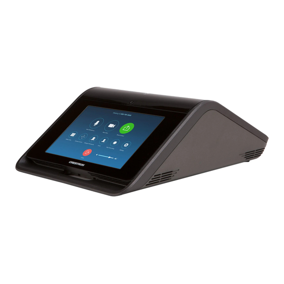
UC-M150-Z
Crestron Flex Tabletop UC Video Conference System for Zoom Rooms™ Software
The Crestron® UC-M150-Z Tabletop UC Video Conference System for Zoom Rooms™ software
delivers a powerful, professional solution for knowledge workers who want the Zoom Rooms
software experience in small to midsize meeting and conference rooms.
The UC-M150-Z comes with a UC-BRKT-100-Z-ASSY Wall Bracket Assembly which contains an
HD-CONV-USB-200 HD to USB Video Converter, UC-ENGINE-Z, and required mounting
hardware. This solution also comes with the cables required for the installation.
To use the UC-M150-Z system you must have a Zoom Rooms™ software account.
D u
U C
a l
H D
- B
D i s
M I
R K
p l a
T - 1
0 0
H D
- Z -
C O
A S
S Y
N V
U S
B 2
0 0
U S
B 3
U C
. 0
E N
G I N
E Z
C C
S
C A
T 5
C A
T 5
Check the Box
Item
UC-M150-Z
CBL-CAT5E-7, 7 ft (2.1 m) CAT5e Cable (P/N 6509924)
CBL-HD-20, 20 ft (6.1 m) HDMI® Cable (P/N 6503567)
CBL-HD-THIN-HS-6, 6 ft (1.8 m), Thin HDMI Cable (P/N 6508218)
CBL-USB-A-EXT-15, 15 ft (4.57 m) USB Extension Cable, Type A Male-to-Female,
(P/N 6508260)
CBL-USBC-HD-9, 9 ft (2.7 m) USB 3.0 to HDMI converter cable (P/N 6510718)
CCS-CAM-USB-F-400, Huddly IQ™ Collaboration Camera (P/N 6510482)
CCS-UC-1, Crestron Mercury® Tabletop UC Conference Console (P/N 6508227)
CCS-UCA-KB-USB Wireless Keyboard with Touchpad (P/N 6509547)
CCS-UCA-MEM-USB, Zoom Rooms USB Stick (P/N 6509548)
PW-2420RU, Desktop Power Pack, 24VDC, 2.5A (P/N 6500187)
UC-BRKT-100-Z-ASSY Wall Bracket Assembly (includes HD-CONV-USB-200,
CBL-MDP-HD-0.5, UC-CONN-HD, and UC-ENGINE-Z, Connector Cover Screws with
Tools, and Mounting Hardware) (P/N 6511049)
Additional Requirements
The following items are required to build a Flex system.
•
A Zoom Rooms account
•
A video display, connected to the UC-ENGINE-Z
•
#1 Phillips screwdriver
•
Drill with a 5/16 in. bit (required for use with mounting anchors)
Optional Items
The following can be added to a Flex system.
•
A secondary display, connected to the UC-ENGINE-Z
•
CCS-UCA-SMK Swivel Mount Kit
•
CCS-UCA-MIC Microphone Pods
Install the Wall Bracket Assembly
y
The wall bracket assembly can be installed on a wall behind a display device, or attached to
the rear of the display device. The wall bracket assembly includes mounting slots on both side
edges, spaced 100, 200, and 300 mm vertically, to allow for attachment to either side of the
display mounting plate. Additional mounting holes are provided on each side for other mounting
locations. Centerline mounting holes are also provided for attachment to the building structure.
H D
Integrated, reusable cable tie wraps manage cable runs between the wall bracket and peripheral
M I
devices.
Dimensions
C A
M
U S
e
B
F
4 0
0
e
16.00 in.
Qty
(406 mm)
(170 mm)
1
1
1
1
1
15.44 in.
(392 mm)
1
1
1
1
1
1
1
NOTES:
•
The integrated cable tie wraps are reusable. Take care to avoid damage to the cable tie
wraps.
•
The wall bracket assembly has an opening and pass-through screw holes for placement
over a US electrical wall box that can be covered by a decorative wall plate. If the wall
plate opening will be positioned over an electrical wall box, longer screws will be needed
to secure the decorative wall plate to the electrical box. Do not secure the wall bracket
assembly with the wall plate opening screws.
14.00 in.
(356 mm)
13.45 in.
(342 mm)
7.00 in.
(178 mm)
Reusable Cable Tie Wrap (x4)
Connector Cover
HD-CONV-USB-200
UC-ENGINE-Z
6.70 in.
Connector Cover
Wall Plate Opening
Power Pack
5.00 in.
(127 mm)
13.42 in.
(341 mm)
When mounting on a wall, the wall bracket assembly should be anchored to the wall. The screws
and anchors included with the assembly are best suited for surfaces with 3/8 in. to 3/4 in. (9 mm
to 19 mm) thickness. To use the included anchors, perform the following procedure.
1.
Drill a 5/16 in. (8 mm) pilot hole.
2.
Fold the anchor in the middle and pinch
the ends together.
3.
Insert the anchor in the hole and tap flush
with the wall.
Install the Wall Bracket Assembly On a Wall
14.92 in.
(378 mm)
4.
Insert the included anchor key to pop the
anchor open and lock it behind a hollow
wall.
WARNING:
Do not force or hammer the
key.
5.
Drive the screw part of the way into the
anchor, leaving approximately 1/4 in.
(6 mm) of the screw exposed.
6.
Repeat steps 1 through 5 for the other
anchor.
7.
Place the wall bracket assembly on the
screws and hand tighten the screws until
the wall bracket is secured to the wall.
Advertisement
Table of Contents

Related Manuals for Crestron UC-M150-Z


Summary of Contents for Crestron UC-M150-Z
- Page 1 This solution also comes with the cables required for the installation. wall. the ends together. • A secondary display, connected to the UC-ENGINE-Z To use the UC-M150-Z system you must have a Zoom Rooms™ software account. WARNING: Do not force or hammer the key. •...
- Page 2 07/22/19 Tel: 888.CRESTRON their products. Crestron disclaims any proprietary interest in the marks and names of others. Crestron is not responsible for Certain Crestron products contain open source software. For specific information, please Fax: 201.767.7576 Specifications subject to errors in typography or photography.
Need help?
Do you have a question about the UC-M150-Z and is the answer not in the manual?
Questions and answers