Table of Contents
Advertisement
Quick Links
®
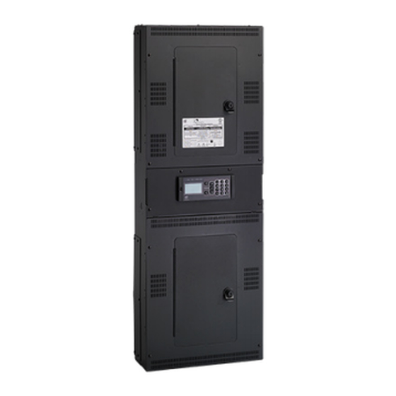
Unison Echo
Relay Panel
Feedthrough
Installation Manual
Revision B
This product is intended for professional use only.
Read this entire document before using this product.
Copyright © 2015 Electronic Theatre Controls, Inc.
All rights reserved. Product information and specifications subject to change.
Part Number: 7123M2102 Rev: B
Released: 2015-12
Advertisement
Table of Contents

Subscribe to Our Youtube Channel
Related Manuals for ETC Unison Echo ERP-FT Series


Summary of Contents for ETC Unison Echo ERP-FT Series
- Page 1 ® Unison Echo Relay Panel Feedthrough Installation Manual Revision B This product is intended for professional use only. Read this entire document before using this product. Copyright © 2015 Electronic Theatre Controls, Inc. All rights reserved. Product information and specifications subject to change. Part Number: 7123M2102 Rev: B Released: 2015-12...
- Page 2 All other trademarks, both marked an d no t ma rked, are the property of thei r respective owners. ETC i ntends th is do cument, whether p rinted o r electroni c, to be provi ded i n its entirety.
-
Page 3: Table Of Contents
Ride-Thru Option ....... 4 Help from ETC Technical Services ....5 C h a p t e r 1 Prepare for Installation . - Page 4 Option card installation location ....18 Primary/Secondary switch ..... . . 18 Connect data wiring.
-
Page 5: Introduction
Introduction Congratulations on your purchase of the ETC Echo Relay Panel Feedthrough (ERP-FT.) Echo Relay Panels continue ETC's tradition of providing the highest quality products for the entertainment and architectural lighting market. Using this Manual This manual contains procedures for field installation of the Echo Relay Panel Feedthrough, and additional relays. -
Page 6: Product Variants
Product Variants This manual contains the procedures for installation of the Echo Relay Panel Feedthrough (ERP-FT). Dimension Model # Description Relay Type Voltage (inches) 120V, 230V, or Small panel with 24 17.14 x 6.3 x ERP24-F242 WR6161-81 277V 1P relays 26.24 50/60Hz Dimension... -
Page 7: 0-10V Dimming Control
Option kits available for the Echo Relay Panel Feedthrough (ERP-FT) include: Model Description Notes WR6161-81, 20A @ 300V AC, ERPFT-1PRK field installed relay kit single pole, single space relay kit WR6166-81, 20A @ 300V AC, ERPFT-2PRK field installed relay kit double pole, single space relay kit WR6172-84, 30A @ 480V AC, ERPFT-3PRK... -
Page 8: Dali Control
DALI Control The Digital Addressable Lighting Interface Control card (ERP-FT-DALI) controls 24 loops of 64 DALI compatible ballasts in broadcast mode. Each loop of up to 64 ballasts are linked one to one with the relay panel circuit for power control. -
Page 9: Help From Etc Technical Services
If you are having difficulties, your most convenient resources are the references given in this manual. To search more widely, try the ETC Web site at www.etcconnect.com. If none of these resources is sufficient, contact ETC Technical Services directly at one of the offices identified below. Emergency service is available from all ETC offices outside of normal business hours. - Page 10 Echo Relay Panel Feedthrough Installation Manual...
-
Page 11: Prepare For Installation
Chapter 1 Prepare for Installation For proper operation of your Echo Relay Panel Feedthrough, ensure that the intended installation location conforms to the following environmental and electrical requirements. Installation Environment • Dry room (10-90% humidity, non-condensing), 0-40°C (32-104°F) ambient temperature, dust free. -
Page 12: Clearance
Clearance • ERP24-FT suggested mounting 48” (1,231mm) height to bottom of the Relay Panel. • ERP48-FT suggested mounting 24” (609.6mm) height to bottom of the Relay Panel. • Clearance on left and right side of the panel should be 1.5” (38.46mm). Zero clearance required if mounted next to another relay or dimming rack. -
Page 13: Compliance
Compliance UL Listed UL508 file #E92154, UL924 file #E242514 This device complies with part 15 of the FCC Rules. Operation is subject to the following two conditions: (1) This device may not cause harmful interference, and (2) this device must accept any interference received, including interference that may cause undesired operation. -
Page 14: Relay Ratings
• ERP-FT with cover(s) and locking door(s) attached with key(s). • Relay panel interior(s) with the quantity and type of relay ordered • DMX Preparation Kit - ETC part number 4100A1002 • Echo Relay Panel Feedthrough Installation Manual Note: Accessory options are packaged separately. -
Page 15: Cable Specification
Cable Specification Purpose Cable Type / Description Note A dedicated circuit is recommended. 8A for the 120V, 230V, or 277V AC ERP24-FT and 15A for the ERP48-FT. Power Control 50/60Hz For installations utilizing UL 924 for emergency Processor Electronics lighting loads, secure a dedicated emergency circuit. - Page 16 Echo Relay Panel Feedthrough Installation Manual...
-
Page 17: Installation Procedure
Chapter 2 Installation Procedure Install Mounting Hardware Step 1: Remove the front cover(s) with locking doors to reveal the relay panel interior. Step 2: Hold the Relay Panel to the desired mounting location. Step 3: Mark the keyhole locations on the wall with a pencil. •... -
Page 18: Mount The Relay Panel
• ERP48-FT requires six 6-8mm (1/4” - 3/8”) bolts or screws, 50-100mm (2-4”) long and suitable wall plugs. - Both the surface and mounting hardware must support 45.36kg (100lbs). - Expose at least 25mm (1”) of threads for mounting the Relay Panel. Mount the Relay Panel Step 1: Mount the ERP-FT enclosure to the installed mounting bolts. -
Page 19: Connect Line And Load Wiring
Connect Line and Load Wiring ERP-FT is shipped standard with either 24 or 48 relays installed. Depending on customer requirements the relay type and quantities may vary for custom orders. Three relay types are available for customer convenience, 20A single pole relay (Aromat WR6161-81), a 20A double pole relay (Aromat WR6166-81) and a 30A 480V double pole relay (WR6172-84). -
Page 20: Connect Control Electronics Power Wiring
Relay Panel. This is an accessory option, sold separately, and available for use when local code requires. Contact ETC for assistance. Step 3: Repeat this process for the remaining Line and Load wires for the installation. -
Page 21: Connect Power Pigtail For Erp48-Ft
Connect power pigtail for ERP48-FT A spiral wrapped cable is hard wired to the transformer in the top panel of the and ERP48-FT and connects to the transformer in the lower panel. This connection is made at the factory prior to shipment of standard 48 Relay Panels. When non-standard ERP48-FT units are shipped from the factory this connection must be completed by the installing contractor. -
Page 22: Install Option Cards
Install Option Cards Each option card is packaged separately and comes with its own installation instructions. Option card installation location Network Option Card DALI Option Card or 0-10V Option Card Contact Input Ride Thru Option Card Option Primary/Secondary switch When using two of either the 0-10V or DALI control Primary/ Secondary option cards in an ERP48-FT you will need to position... -
Page 23: Connect Data Wiring
Connect data wiring Data and Control Wire Specification Purpose Recommended Cable Notes or equivalent (contact ETC for list of DMX In and equivalents). DMX is RS485 serial and can DMX Pass-Thru Belden 9729 be installed in series (i.e. daisy-chain) (J8 and J9) topology. -
Page 24: Dmx Control Wiring And Termination
DMX Control Wiring and Termination DMX wire preparation will vary with the type of wire and termination kit being utilized. Please refer to the instructions provided with the DMX termination kit for specifics on the wire preparation. DMX termination is made to J8 and J9 on the termination board. If daisy-chaining to another rack or From DMX... -
Page 25: Connect Echoconnect
The total combined length of a EchoConnect wire run cannot exceed 1,640 feet (500m), with a maximum distance of 1,313 feet (400m) between any two devices. For systems utilizing Echo Preset stations, ETC recommends terminating the station data run to the Echo host product with the station power supply enabled. - Page 26 To terminate Category 5 cable to the Echo Relay Panel, you will need to use a Unison EchoConnect Cat5 ERP Termination Kit, ETC part# 7186A1208. For instructions on installing this kit, please reference the Echo Relay Panel Cat5 Termination Kit Installation Guide. ETC manuals can be downloaded at www.etcconnect.com.
-
Page 27: Chapter 3 Final Installation And Power Up
Power Control Processor Configuration Manual Reference the for configuration and system test information. If you have any difficulties installing your system, please contact ETC Technical Services at the page 5 office nearest you. ETC contact information is located on of this document. - Page 28 Service: (DE) techserv-hoki@etcconnect.com Hong Kong Tel +852 2799 1220 Service: (Asia) service@etcasia.com Web: www.etcconnect.com Copyright © 2015 ETC. All Rights Reserved. 7123M2102 Rev B Released 2015-12 Product information and specifications subject to change. ...
Need help?
Do you have a question about the Unison Echo ERP-FT Series and is the answer not in the manual?
Questions and answers