Table of Contents
Advertisement
Advertisement
Table of Contents

Related Manuals for Eventide BD500


Summary of Contents for Eventide BD500
-
Page 3: Table Of Contents
Contents Chapter 1 Introducing the BD500 ..................1 Front Panel Rear Panel Audio Connections Chapter 2 Operation ......................5 Installation Rack Mount Connect AC and Turn On Power Switch Level Meters Connect Audio Inputs Connect Audio Outputs Understanding BD500 Profanity Delay Functions... -
Page 5: Chapter 1 Introducing The Bd500
The BD500 has some special functions to make it convenient to use: the WAIT AND EXIT function can be used to synchronize to a network or live signal feed, and the RAMP TO ZERO function can be used to decrease the delay time to 0.00 gradually after it is no longer needed for a safety margin. -
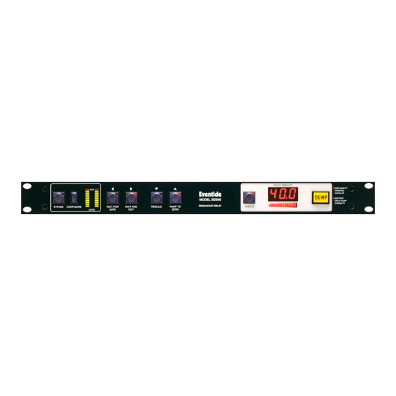
Page 6: Front Panel
A for configuration mode information. SNEEZE button Since the BD500 can serve as a broadcast profanity If the unit is configured as a profanity delay, this delay or as a precision fixed delay, many of the buttons button is used to cut off microphone audio. If delay is have dual purpose. -
Page 7: Rear Panel
XLR audio inputs to the XLR Input data, XLR (optional) audio outputs. This does not guarantee that high volt- The BD500's connector is female. Pin 1 is shield, 2 age will not be present in the unit. Always disconnect and 3 are differential. -
Page 8: Audio Connections
Pin 1 is grounded. Pin 2 is +phase and pin 3 is –phase. Even though the inputs of the BD500 are balanced, you can still use them with an unbalanced line. The BD500 XLR analog audio input connectors are fe- pin 3 male. -
Page 9: Chapter 2 Operation
Normally the BD500 will be mounted in a standard 19-inch rack using grommets to avoid damaging the front panel overlay. The BD500 should be supported at the rear. The rack should be well ventilated and in a dry and dust free environment so heat and moisture won't cause damage or degradation of performance. -
Page 10: Connect Audio Inputs
If your audio source cannot be adjusted or does not have the range to achieve a low enough or high enough signal, you must adjust the BD500's input trim. The BD500 has up to 48dB of input trim which is controllable from the front panel configuration mode. -
Page 11: Understanding Bd500 Profanity Delay Functions
At the start the play head and record head overlap (no delay). The record head is slowly moved to the left until 8 seconds of delay exists. The Eventide patented rebuild process does this in about 120 sec- onds without causing a pitch change in the audio. -
Page 12: Operation As A Profanity Delay
Which indicators are lit changes depending on what state (or mode) the BD500 is in. Since the unit is at 0.00 delay and in-line it will be in live mode. -
Page 13: Starting A Show Segment With Wait For Safe
Note: During the 4-second period that wait for safe is running and the WAIT FOR SAFE button's indicator is flashing, the microphone audio is passed directly to the BD500 outputs. It is usually undesirable to have that audio pass over the air. Use a mixer or other control to disable that audio until the show is scheduled to start. -
Page 14: Dump Button
The display is configurable to be blank, or to show 1, 2 or 3 digits of resolution of delay length. In bypass the display will show the safe time. Page 10 Chapter 2 Operation BD500 Broadcast Profanity Delay ©Eventide Inc. 1995-1999 doc release 10... -
Page 15: Operation As A Precision Fixed Delay
Operation as a Precision Fixed Delay The BD500 may be used as a fixed stereo delay line, adjustable from 0.000 seconds to 8.000 seconds. Opera- tion is straightforward with several front panel buttons serving secondary duty as fixed delay controls. - Page 16 Page 12 Chapter 2 Operation BD500 Broadcast Profanity Delay ©Eventide Inc. 1995-1999 doc release 10...
-
Page 17: Chapter 3 Configuration
This chapter covers the configurable variables that needed for the basic BD500. Configuration of optional features is covered in the appendices. Operation of the configuration mode is via the front panel buttons. All of the buttons are used to navigate through a map of configuration variables. -
Page 18: Table Of Configuration Variables
Oscillator and Pause, or Pause only method P,O P If Pause only is selected, rebuild or ramp to zero progress is made only during periods of silence. Page 14 Chapter 3 Configuration BD500 Broadcast Profanity Delay ©Eventide Inc. 1995-1999 doc release 10... - Page 19 Note: Configuration for optional features is discussed in the Appendices. For optional audio features, see Appendix A. For optional remote control features, see Appendix C. BD500 Broadcast Profanity Delay Chapter 3 Configuration Page 15 ©Eventide Inc. 1995-1999 doc release 10...
-
Page 20: Configurable Variables
(car-phone audio or wind noise). eliminated. Since the operator really only needs to know that the BD500 is in rebuild, and whether it is Output Level safe or not, the operator may choose not to have the This controls attenuation in the analog and digital delay time presented in such high resolution. - Page 21 ( ). If one channel is usually The ramp to zero time is how long the BD500 will of poorer quality (i.e., a telephone), give the other need to go from maximum delay to 0.00 delay. This is channel priority.
- Page 22 Page 18 Chapter 3 Configuration BD500 Broadcast Profanity Delay ©Eventide Inc. 1995-1999 doc release 10...
-
Page 23: Appendix A Optional Aes/Ebu Digital Audio
BD500 derives the sample rate from the input AES/EBU signal. If AES/EBU is selected and there is no digital audio signal present, the unit will declare an out-of-lock con- dition. -
Page 24: Notes And Warnings For Aes/Ebu Operation
The BD500's purpose is to store audio and play it back with a delay. If the rate of audio into the unit changes while audio is stored, the audio played from the delay will change pitch. Thus if the AES/EBU source's sample... -
Page 25: Remote Connector
Appendix B Basic Remote Control The BD500 with the basic remote control feature has inputs for DUMP and SNEEZE and outputs to indi- cate safe and dump. pin 8 pin 1 pin 15 pin 9 Basic Rear Panel Remote Control Connector... - Page 26 Page 22 Appendix B Basic Remote Control BD500 Broadcast Profanity Delay ©Eventide Inc. 1995-1999 doc release 10...
-
Page 27: Appendix C Optional Remote Control/Signalling
Also see Appendix A. Remote Connector This is a 15-pin female DB15 connector which allows 7 inputs to the BD500 and 4 outputs. All front panel buttons are available for external control. In addition, outputs are provided on this connector to drive relays which may be used for indicator lights and to enable audio signals. -
Page 28: Configuring Optional Rear Panel Inputs And Outputs
The assignment of the input lines to various commands is handled by the configuration mode. The remote outputs are also configurable to signal many different conditions in the BD500. If the remote conotrol option is installed the configuration mode will have an additional level of configurable items. - Page 29 BD500 is still performing the previous function. When mute is no longer asserted the unit returns to the previous mode.
- Page 30 Press the BYPASS button to put the unit in-line. Now press WAIT FOR SAFE. The unit will quickly attain the safe condition. When the BD500's front panel DUMP button illuminates, the relay should close. Once this happens, press your new remote DUMP button. The delay should be reduced by the dump amount.
-
Page 31: Appendix D Optional Auxiliary Connector For Control Signal Delay
Notes: • The field contact supply output is a BD500 supplied voltage to be used to trigger the BD500's auxiliary in- puts. This would be used for one side of a dry contact (switch or relay), the other side of which would go to one of the BD500's auxiliary inputs. - Page 32 Page 28 Appendix D Optional Auxiliary Port BD500 Broadcast Profanity Delay ©Eventide Inc. 1995-1999 doc release 10...
-
Page 33: Appendix E Optional Rs-232 Control
The BD500 only sends messages as a response to a poll from a host computer. The host computer must not send a message unless it has received a > character (hex 3E) or unless it has not heard from the BD500 in 100mS. - Page 34 ..send delay amount in hexadecimal using 3 characters of ASCII/hex followed by >. Eventide Factory Defaults ... request factory defaults for all config variables. Note: Allow 400mS before "!>" W initiates wait for safe ....Note: when the unit reaches safe, it will switch to rebuild mode.
- Page 35 Changes to those variables are not go to static at current delay switches to bypass mode used by the BD500 audio processor until the unit goes W initiates wait for safe into and out of 0 delay or bypass.
- Page 36 Page 32 Appendix E Optional RS-232 Control BD500 Broadcast Profanity Delay ©Eventide Inc. 1995-1999 doc release 10...
-
Page 37: Appendix F Diagnostics
Appendix F Diagnostics • Put up " " message. The BD500 has software features designed to aid • Check power supply voltage. If measures out of range, debugging the system hardware. Some of these fea- display error message. tures may be used to assist in analyzing end-user setup •... -
Page 38: Startup Switches
Startup Switches The BD500 has operations which are used in the factory to prepare the unit to be shipped. Each operation is performed by turning on the unit while holding down a button until the message goes away. Turn off "Hide Fatal Error" option - WAIT AND EXIT key... -
Page 39: Error Codes
The test reports that a memory failure was found during the first read back cycle. The error was detected when the dynamic RAM was accessed using the X select line. BD500 Broadcast Profanity Delay Appendix F Diagnostics Page 35 ©Eventide Inc. 1995-1999... - Page 40 This does not indicate a memory since the last power-up. failure although there may be a short between memory select lines and processor control lines. Page 36 Appendix F Diagnostics BD500 Broadcast Profanity Delay ©Eventide Inc. 1995-1999 doc release 10...
- Page 41 The second read did not verify. suitable to be used with the installed audio card. The origi- nal BD500 audio card could be supported with this size The factory burn-in coprocessor external memory test pro- DSP. The installed audio card needs more RAM for sup- gram was uploaded to the coprocessor during start-up, in port.
- Page 42 CPU initiating it, or that the motherboard program has a bug and somehow got out of the transmit function without waiting for the data bits to be clear. Page 38 Appendix F Diagnostics BD500 Broadcast Profanity Delay ©Eventide Inc. 1995-1999 doc release 10...
- Page 43 DSP boot code or there is an intermittent problem in the coprocessor<->motherboard processor host port or with the coprocessor CPU itself. The coprocessor external memory is not involved in this failure. BD500 Broadcast Profanity Delay Appendix F Diagnostics Page 39 ©Eventide Inc. 1995-1999 doc release 10...
- Page 44 The coprocessor external memory is not involved in this gram was not uploaded successfully. The program was failure. read back and showed to have errors during upload. This is not supposed to happen. Page 40 Appendix F Diagnostics BD500 Broadcast Profanity Delay ©Eventide Inc. 1995-1999 doc release 10...
- Page 45 This looks like a programming bug but might (unlikely) have been caused by a hardware problem on the motherboard. BD500 Broadcast Profanity Delay Appendix F Diagnostics Page 41 ©Eventide Inc. 1995-1999...
- Page 46 The User Interface program reports a firmware error where ware error. a change state was issued with the same state number as the previous state. Page 42 Appendix F Diagnostics BD500 Broadcast Profanity Delay ©Eventide Inc. 1995-1999 doc release 10...
- Page 47 The origi- the coprocessor was hung up processing the previous nal BD500 audio card could be supported with this size message (TxRDY/TxEMPTY). This indicates that the co- DSP. The installed audio card needs more RAM for sup- processor did something or that the motherboard program port.
- Page 48 A firmware or hardware error oc- curred that triggered this but a further error must exist in order to reach this message. Page 44 Appendix F Diagnostics BD500 Broadcast Profanity Delay ©Eventide Inc. 1995-1999 doc release 10...
-
Page 49: Appendix G Specifications
500mA individually, or 200mA each with all outputs driven Remote inputs 1mA at 4.5v minimum, 25v max These specifications are subject to change without notice. BD500 Broadcast Profanity Delay Appendix G Specifications Page 45 ©Eventide Inc. 1995-1999 doc release 10... - Page 50 Page 46 Appendix G Specifications BD500 Broadcast Profanity Delay ©Eventide Inc. 1995-1999 doc release 10...
-
Page 51: Appendix H Warranty Information
The warranty does not cover damage or defects due to accident or abuse. The BD500 is a complex piece of equipment that does not react well to being dropped, bounced, crushed, soaked or exposed to excessively high voltages. If the unit becomes defective for these or similar causes, and the unit is deemed to be economically repairable, we will repair it and charge our normal rates. - Page 52 Who performs warranty work The only company authorized to perform work under this warranty is Eventide, Little Ferry, NJ. While you are free to give it to anyone (or to work on it yourself), we will not honor claims for payment for labor or parts from you or from third parties.
-
Page 53: Index
Index Symbols 0-R symbol - ramp to zero/rebuilt bar graph twin, on left. See level meters on config level mote under 3 digit display. See display configuring RCC 24 basic remote control 21 0DB symbol - zero decibels BD symbol - broadcast delay indicates no attenuation 14. - Page 54 D-R symbol - dump to rebuild E-R symbol - ramp to exit/rebuild in config level 6remote in config level mote to configure RCC input 24 to configure RCC input 24 decrease the delay ERR symbol - error ramp to zero. See ramp to zero flashing on front panel 34 wait and exit.
- Page 55 increase the delay maximum delay. See full delay rebuild. See rebuild maximum length 16 wait for safe. See wait for safe modes of operation 8 INL symbol - in line motherboard status LEDs in config level 1inline used during startup 33 setting power up mode 14 MUT symbol - muting audio INP symbol - input attenuation...
- Page 56 P symbol - Pause R1 symbol - right 1 in config level 4processing in config level 4processing while selecting oscillator mode 14 selecting source for processor input 15 P-- symbol - password ?? rack 5 on entry to config mode ramp to bypass asking for password 13 explanation 25...
- Page 57 34 set up RCC command input 24 reset set up RCC output signal 25 the bd500. See start-up sequence self test response to a fatal error during startup. See diagnostics: built-in controlling 34 production 34 restoring factory defaults.
- Page 58 tape recorder analogy 7 symbol - wait and exit TESTS in config level displayed during startup 33 setting the config password 14 tests in config level mote self test during startup. See diagnostics: built-in set up RCC command input 24 THD.
Need help?
Do you have a question about the BD500 and is the answer not in the manual?
Questions and answers