Advertisement
SPECIFICATION
MODEL
POWER SOURCE
FREQUENCY ( Hz )
MOTOR POWER
DIMENSIONS (W x L x H)
NETT WEIGHT (kg)
CLOSE SUCTION
EXTENSION WANDS
FLOOR NOZZEL
ATTACHMENTS
CONTENTS
SPECIFICATION..........................................................................
SCHEMATIC DIAGRAM..............................................................
EXPLODED VIEW........................................................................
REPLACEMENT PARTS LIST.....................................................
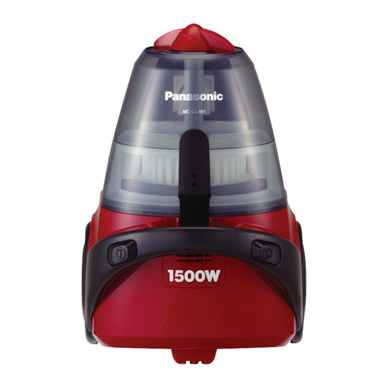
MC-CL481
MC-CL481
1400W/1500W/1600W
5.0 kg
Metal X 2 / Plastic X 2
2-Step
Hose, Extension Wand, Floor Nozzle, Curved Ward, Crevice Tool, Dusting Brush
Page
MC-CL483
120V/220V/220-240V/230-240V/230V/240V
50/60Hz, 50Hz
290mm X 425mm X 317mm
1650mmH2O Or More.
Telescopic / Metal X 2
Turbine / 2-Step
1
ATTACHMENT EXPLODED VIEW..................................................
2
ATTACHMENT REPLACEMENT PART LIST.................................
3
DISASSEMBLY PROCEDURES......................................................
4-5
PACKING INSTRUCTION AND PACKING LIST..............................
Order Number: PMMA080102C3
Vacuum Cleaner
MC-CL481
MC-CL483
MC-CL485
MC-CL483/MC-CL485
1400W/1800W
5.1 kg
© 2008 Panasonic Manufacturing Malaysia Berhad
(6100-K). Unauthorized copying and distribution is a
violation of law.
MC-CL485
Telescopic
Turbine
Page
6
6
7-12
13
Advertisement
Table of Contents

Related Manuals for Panasonic MC-CL481


Summary of Contents for Panasonic MC-CL481
- Page 1 Page SPECIFICATION................ATTACHMENT EXPLODED VIEW..........SCHEMATIC DIAGRAM.............. ATTACHMENT REPLACEMENT PART LIST......... EXPLODED VIEW................ 7-12 DISASSEMBLY PROCEDURES............PACKING INSTRUCTION AND PACKING LIST......REPLACEMENT PARTS LIST............. © 2008 Panasonic Manufacturing Malaysia Berhad (6100-K). Unauthorized copying and distribution is a violation of law.
-
Page 2: Schematic Diagram
SCHEMATIC DIAGRAM MODEL:CL481 (EURO/UK/SWITZERLAND) (SAUDI ARABIA) (MALAYSIA/HONG KONG/SINGAPORE THAILAND/KUWAIT/MID EAST/IRAN) MODEL:CL483/485 (MALAYSIA/HONG KONG/SINGAPORE (EURO/UK/SWITZERLAND) THAILAND/KUWAIT/MID EAST/IRAN) -
Page 3: Exploded View
EXPLODED VIEW... -
Page 4: Replacement Parts List
REPLACEMENT PARTS LIST MODEL REF. NO. PART NAME PART NO. REMARKS MC-CL481 MC-CL483 MC-CL485 BUCKLE YMV01D63000 BUCKLE SPRING YMV04D61000 SUCTION INLET YMV60H61000 VALVE GROMMET YMC50KSG000 FILTER KNOB YMV35K610S0 SILVER FILTER KNOB YMV35K610R0 FILTER KNOB YMV35K610B0 BLUE DUST COMPARTMENT ASSY YMV88K610S0... - Page 5 REPLACEMENT PARTS LIST FRONT COVER YMV01H61000 FILTER YMV30K61000 FILTER SUPPORRTER YMV32K61000 BODY PARTITION UNIT YMV96A63000 BODY PARTITION UNIT YMV96A6300U BRAKE LEVER UNIT YMV94N61000 SPRING BRAKE BUTTON YMV71N61000 BRAKE PEDAL YMV04E61000 WHEEL YMC01CLE0V0 WHEEL YMV01C61000 SOFT WHEEL CORD REEL UNIT YMV99N61008 UK, MALAYSIA, H.KONG, S.ARBIA, KUWAIT CORD REEL UNIT YMV99N6100E...
- Page 6 ATTACHMENT EXPLODED VIEW ATTACHMENT REPLACEMENT PART LIST MODEL REF. NO. PART NAME PART NO. REMARKS MC-CL481 MC-CL483 MC-CL485 HOSE ASS'Y AMC94P-6L0V0 HOSE UNIT AMC84P-6L0V0 CURVED WAND AMC30P-0R0V0 NO HOLE CURVED WAND V30P61000 HOLE SUCTION REGULATOR AMC54P-7K0V0 HOSE SUPPORTER AMC24P-0R0V0 CONNECTION PIPE...
-
Page 7: Disassembly Procedures
DISASSEMBLY PROCEDURES Push the Buckle forward. (Fig.1) (Fig.1) Pull the Dust Compartment Assembly upward. (Fig.2) (Fig.2) Remove the Crevice Tool from it compartment. (Fig.3) (Fig.3) Remove the 4 pcs screw for Lower Body. (Fig.4) (Fig.4) - Page 8 DISASSEMBLY PROCEDURES Pull up the Upper Body Assy. (Fig.5) (Fig.5) Remove the Caster Unit by a minus (-) screwdriver. (Fig.6) (Fig.6) Remove the Filter Support from the compartment. (Fig.7) Note:- Check the condition of the filter, if damage change a new piece. (Fig.7) Remove the Motor Cover Unit from the Lower Body.
- Page 9 DISASSEMBLY PROCEDURES Remove the Motor Unit from the Motor Cover. (Fig.9) (Fig.9) Pull the Wire Terminal from the Motor unit. (Fig.10) Note:- Pull the wire terminal, do not pull the wire because it may break off from it terminal. (Fig.10) Remove Cord Reel Unit upward.
- Page 10 DISASSEMBLY PROCEDURES Take out the Metal Case plate. (Fig.13) (Fig.13) Remove the P.C.B. (Fig.14) (Fig.14) Pull the Filter Ass’y as shown in the diagram. (Fig.15) (Fig.15) Push the lock at Slider Supporter to remove the Pre- Filter. (Fig.16) (Fig.16)
- Page 11 DISASSEMBLY PROCEDURES Clean the Filter Unit by turning the Slider clockwise and anticlockwise. (Fig.17) (Fig.17) Turn the Dust Compartment Assembly up side down and remove 2 pcs screw. (Fig.18) (Fig.18) Push inside the Dust Compartment and pull the suction Inlet upward. (Fig.19) (Fig.19) Remove the 2 pcs screw from bottom...
-
Page 12: Reassembly Procedures
DISASSEMBLY PROCEDURES Remove the Handle Cover. (Fig.21) (Fig.21) Remove the 2 pcs screw from bottom Upper Body . (Fig.22) (Fig.22) Remove the Indicator Plate. (Fig.23) (Fig.23) Remove the Indicator Unit. (Fig.24) (Fig.24) REASSEMBLY PROCEDURES Assemble in reverse order. REMINDER Above are the complete disassembly procedure, for certain repairing method you might not need to dismantle other unnecessary part. -
Page 13: Packing Instruction
PACKING INSTRUCTION EXTENSION WAND INSTRUCTION MANUAL HOSE BODY BAG FLOOR NOZZEL CUSHION B MAIN BODY (SET) CUSHION A HOSE CONNECTION WAND CURVED WAND DUSTING BRUSH CREVICE TOOL CARTON BOX PACKING LIST REF. NO PART NAME PART NO. REMARKS CARTON BOX V61Z6100E CONTINENTAL, UK, SWITZERLAND CARTON BOX...
Need help?
Do you have a question about the MC-CL481 and is the answer not in the manual?
Questions and answers