Table of Contents
Advertisement
Quick Links
Instruction Manual
Form 5666
January 2016
Type ACE95jr Tank Blanketing Valve
Introduction
WArnIng
!
Failure to follow these instructions or
to properly install and maintain this
equipment could result in an explosion,
fire and/or chemical contamination
causing property damage and personal
injury or death.
Fisher
Tank blanketing valves must
®
be installed, operated and maintained
in accordance with federal, state and
local codes, rules and regulations
and Emerson Process Management
regulator Technologies, Inc.
(Emerson™) instructions.
If the valve vents gas or a leak develops
in the system, service to the unit may be
required. Failure to correct trouble could
result in a hazardous condition.
Installation, operation and maintenance
procedures performed by unqualified
personnel may result in improper
adjustment and unsafe operation. Either
condition may result in equipment
damage or personal injury. Use qualified
personnel when installing, operating
and maintaining the Type ACE95jr Tank
Blanketing Valve.
Scope of the Manual
This Instruction Manual provides installation, startup
and maintenance procedures for the Type ACE95jr
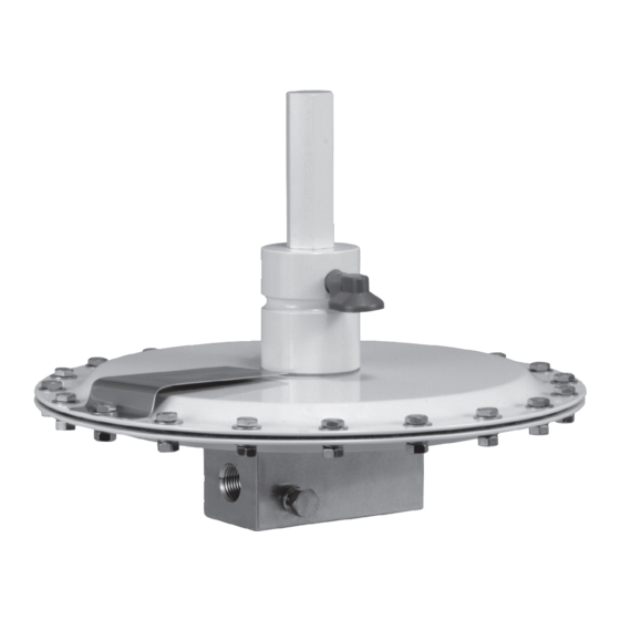
tank blanketing valve. See Figure 1.
W8157
Figure 1. Type ACE95jr Tank Blanketing Valve
Product Description
The Type ACE95jr tank blanketing valve is an
extension of the Type ACE95 tank blanketing valve
and is intended to handle lesser flows on gas
blanketing systems. The valve prevents a stored
product from vaporizing into the atmosphere, reduces
product combustibility and prevents oxidation or
contamination of the product by reducing its exposure
to air. The Type ACE95jr maintains a slightly positive
pressure and thereby reduces the possibility of tank
wall collapse during pump out operations.
www.fisherregulators.com
Type ACE95JR
Advertisement
Table of Contents

Related Manuals for Fisher EMERSON ACE95JR


Summary of Contents for Fisher EMERSON ACE95JR
- Page 1 Fisher Tank blanketing valves must ® be installed, operated and maintained in accordance with federal, state and...
-
Page 2: Specifications
Type ACE95JR Specifications This section lists the specifications and ratings for the Type ACE95jr tank blanketing valve. Factory specifications are stamped on a nameplate fastened to the actuator of the valve. Sizes and End Connection Styles Main Valve Flow Characteristic 1/2 NPT Linear 1 x 1/2 NPT... -
Page 3: Valve Closed
Type ACE95JR POPPET CAgE O-rIng SEAT rOllIng DIAPHrAgM VAlVE ClOSED SEnSIng COnnECTIOn InlET E0205 InlET PrESSUrE VAlVE OPEn ATMOSPHErIC PrESSUrE TO TAnK TAnK PrESSUrE Figure 2. Type ACE95jr Operational Schematic Principle of Operation Installation The Type ACE95jr tank blanketing valve controls the WArnIng vapor space pressure over a stored liquid. - Page 4 Type ACE95JR TYPE ACE95jr BLANKETING GAS SENSING SUPPLY LINE LINE SHUTOFF VALVE LINE STRAINER TYPE 252 INLET FILTER SHUTOFF SHUTOFF VALVE VALVE TANK VENT EMERGENCY TANK VENT BLANKETING GAS TO TANK BLANKETING GAS/VAPOR SPACE TANK E0620 LIQUID Figure 3. Type ACE95jr Tank Blanketing Valve Installation of the national Fire Codes of the national certain the body interior is clean and the pipelines Fire Protection Agency or by other...
- Page 5 Type ACE95JR Piping Considerations Gauges and Shutoff Valves note Inlet gas shutoff valves are desirable for servicing. If this Type ACE95jr tank blanketing valve was not Piping lengths are best when they are ordered with an inlet pressure gauge, it is advisable to kept short with a minimum number of install a gauge between the inlet shutoff valve and the elbows and fittings.
-
Page 6: Monthly Maintenance
Type ACE95JR ADjUSTIng SCrEW (KEy 2) lOCK nUT ACTUATOr CAP (KEy 3) (KEy 1) VEnT (KEy 6) SPrIng CASE (KEy 7) W8160 Figure 4. Spring Case, Adjusting Screw and Actuator Cap Shutdown Be certain that nameplates are updated to accurately indicate any field changes in equipment, materials, Installation arrangements vary, but in any installation service conditions or pressure settings. -
Page 7: Disassembly And Assembly
Type ACE95JR rOllIng DIAPHrAgM (KEy 38) POPPET (STEM) (KEy 42) W8162 CrOSS-DrIllED HOlE PISTOn O-rIng (KEy 37) (KEy 39) CAgE (KEy 52) W8161 Figure 5. Cage Assembly Disassembly and Assembly When performing disassembly or re-assembly operations, refer to Figure 6 for key numbers (unless CAUTIOn otherwise directed). - Page 8 Type ACE95JR 5. Remove the range spring (key 8) and spring seat Cage Sub-Assembly (key 5). A lower range spring (key 162) is used for 1. Install the internal O-rings (key 16) into the body negative pressure values only. (key 18). 6.
-
Page 9: Parts Ordering
Type ACE95JR 4. Place an O-ring (key 14) into the groove of the upper actuator case. Attach the spring case to diaphragm bolt (key 15). the upper actuator case using hex-head screws (key 29). 5. Build the diaphragm sub-assembly with the diaphragm (key 11) and two diaphragm plates 12. - Page 10 Type ACE95JR MAIn VAlVE DETAIl GC950201 lOCATE grOOVE In BODy FOr rOllIng DIAPHrAgM BEAD Figure 6. Type ACE95jr Tank Blanketing Valve Assembly...
-
Page 11: Parts List
Type ACE95JR Parts list Description Part number Description Part number O-ring (2 required) Stainless Steel GC053301X02 Nitrile (NBR) 1F115306992 Ethylenepropylene (EPDM)/FDA 1F1153X0062 Steel GC053301X32 Fluorocarbon (FKM) 1F1153X0022 Adjusting Screw Perfluoroelastomber (FFKM) 1F1153X0032 0.5 to 5 in. w.c. / 1 to 12 mbar GC060216X12 Body (C 0.2) - Page 12 For further information visit www.fisherregulators.com The Emerson logo is a trademark and service mark of Emerson Electric Co. All other marks are the property of their prospective owners. Fisher is a mark owned by Fisher Controls International LLC, a business of Emerson Process Management.
Need help?
Do you have a question about the EMERSON ACE95JR and is the answer not in the manual?
Questions and answers