Table of Contents
Advertisement
Instruction Manual
D103175X012
Fisher
GX Control Valve and Actuator System
™
Contents
. . . . . . . . . . . . . . . . . . . . . . . . . . . . . . . . .
. . . . . . . . . . . . . . . . . . . . . . . . . . . . .
. . . . . . . . . . . . . . . . . . . . . . . . . . . . . . . . .
. . . . . . . . . . . . . . . . . . . . . . . . . . . . . . .
. . . . . . . . . . . . . . . . . . . . . . . . . . . . .
. . . . . . . . . . . . . . . . . . . . . . . . . . . . . . . . .
. . . . . . . . . . . . . . . . . . . . . . . . . . . . . . .
. . . . . . . . . . . . . . . . . . . . . . . . . . . . . . . . . . .
. . . . . . . . . . . . . . . . . . . . . . . . . . . . . . . . . . .
Introduction
Scope of Manual
This instruction manual includes installation, maintenance, and parts information for the Fisher GX control valve and
actuator system.
Do not install, operate, or maintain a GX valve without being fully trained and qualified in valve, actuator, and
accessory installation, operation, and maintenance. To avoid personal injury or property damage, it is important to
carefully read, understand, and follow all the contents of this manual, including all safety cautions and warnings. If you
have any questions about these instructions, contact your
proceeding.
Description
The GX is a compact, state-of-the-art control valve and actuator system, designed to control a wide range of process
gases, vapors, and fluids.
The GX is rugged, reliable, and easy to select. It requires no actuator sizing -- the actuator selection is automatic once
the valve body construction is selected.
The GX meets the requirements of both EN and ASME standards. It is available with a complete accessory package,
including the FIELDVUE DVC2000 integrated digital valve controller.
www.Fisher.com
. . . . . . . . . . . . . . . . . . . . . . . . .
. . . . . . . . . . . . . . . . . . . . . . . .
. . . . . . . . . . . . . . . . . . . . . .
. . . . . . . . . . . . . . . . . . . . . . . .
. . . . . . .
. . . . . . . . .
. . . . . . . . . . . . . . . . . . . . .
. . . . . . . . . . . . . . . . . . . . . . . .
. . . . . . . . . . . . . . . . . . . . . . . .
. . . . . . . . . . . . . . . . . . . . . . . .
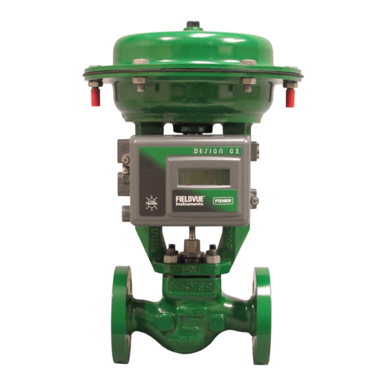
Figure 1. Fisher GX Control Valve, Actuator, and
FIELDVUE DVC2000 Digital Valve Controller
1
1
1
2
2
2
4
5
11
12
13
16
19
24
25
26
41
42
43
W8861
Emerson sales office
GX Valve and Actuator
or Local Business Partner before
July 2017
Advertisement
Table of Contents

Related Manuals for Fisher GX


Summary of Contents for Fisher GX
-
Page 1: Table Of Contents
The GX is a compact, state‐of‐the‐art control valve and actuator system, designed to control a wide range of process gases, vapors, and fluids. The GX is rugged, reliable, and easy to select. It requires no actuator sizing ‐‐ the actuator selection is automatic once the valve body construction is selected. -
Page 2: Specifications
1. For 4.8 to 14 mm ports, Class VI shutoff is achieved without PTFE seat. Educational Services For information on available courses for the Fisher GX valve and actuator system, as well as a variety of other products, contact: Emerson Automation Solutions... - Page 3 Local Business Partner for more complete specifications. Provide the product serial number (shown on the nameplate, figure 2) and all other pertinent information. Figure 2. Fisher GX Nameplate Examples (Key 35) WITHOUT SPRING INFORMATION GE01296‐H (USED PRIOR TO 2009)
-
Page 4: Maintenance
Instruction Manual GX Valve and Actuator July 2017 D103175X012 If hoisting the valve take care to prevent people from being injured in case the hoist or rigging slips. Be sure to use adequately sized hoists and chains or slings to handle the valve. -
Page 5: Actuator Maintenance
Refer to figure 3 and table 2 for proper spring configuration. Note Older GX actuator nameplates do not contain spring configuration information. If you require replacement springs or wish to switch to an optional actuator construction, consult your Emerson sales office or Local Business Partner. - Page 6 Instruction Manual GX Valve and Actuator July 2017 D103175X012 Figure 3. Spring Configuration GG00398-B 6. Remove the short actuator casing cap screws and hex nuts (keys 17 and 18) first. Once these have been removed from the actuator assembly, carefully remove the long actuator cap screws and hex nuts (keys 16 and 18), alternating between them to gradually release the spring energy (compression).
- Page 7 Instruction Manual GX Valve and Actuator D103175X012 July 2017 Actuator Disassembly (For Air‐to‐Close Constructions ‐ see figure 20 or 21) 1. Remove the stem connector nut half (key 23), stem connector bolt half (key 24), and travel indicator (key 26).
- Page 8 Instruction Manual GX Valve and Actuator July 2017 D103175X012 Table 3. Fisher GX Maximum Rated Travel TRAVEL ACTUATOR SIZE NUMBER OF CASING BOLTS 20 or 40 1200 40 or 60 Table 4. Body Nut (Key 7) Torque Requirements TORQUE VALVE SIZE...
- Page 9 Instruction Manual GX Valve and Actuator D103175X012 July 2017 9. If you had previously removed the actuator assembly from the valve, place the actuator assembly back onto the valve body (key 1). Install the four body nuts (key 7), but tighten them only finger‐tight.
- Page 10 Instruction Manual GX Valve and Actuator July 2017 D103175X012 2. Install the diaphragm (key 10) on the diaphragm plate (key 11). Place the diaphragm O-ring (key 109) and the washer (key 15) over the center hole of the diaphragm, so that the convex part of the washer is facing down toward the diaphragm and contains the O-ring.
-
Page 11: Fieldvuet Dvc2000 Digital Valve Controller Mounting
For further detail on the operation and maintenance of the DVC2000, refer to the DVC2000 instruction manual. The FIELDVUE DVC2000 digital valve controller mounts directly to an interface pad on the GX actuator yoke leg, eliminating the need for mounting brackets (see figure 1). Internal passageways in the actuator route the pneumatic output to the actuator casing, which eliminates the need for external air supply tubing in the air‐to‐open... -
Page 12: Packing Maintenance
4. Remove the digital valve controller's cover. 5. Using a 6mm hex wrench, attach the digital valve controller to the GX actuator mounting pad on the side that has the open pneumatic port. Be sure to place the O‐ring seal between the digital valve controller's pneumatic output and the actuator mounting pad (Port B, as shown in figure 4). -
Page 13: Replacing Packing (Pneumatic Actuators)
Instruction Manual GX Valve and Actuator D103175X012 July 2017 Packing Adjustment ™ For ENVIRO-SEAL spring‐loaded single PTFE V‐ring packing (figure 15) or for ENVIRO-SEAL graphite ULF packing (figure 16), the Belleville spring pack (key 34) maintains a sealing force on the packing. If leakage is detected around the packing follower (key 29) check to be sure that the packing follower (key 29) is tight. - Page 14 Instruction Manual GX Valve and Actuator July 2017 D103175X012 WARNING If there is evidence of process fluid under pressure leaking from the joint, retighten the valve body/joint nuts and return to the Warning at the beginning of the Maintenance section to ensure proper steps have been taken to isolate the valve and relieve process pressure, thus avoiding property damage or personal injury.
- Page 15 Instruction Manual GX Valve and Actuator D103175X012 July 2017 CAUTION Inspect the valve stem, threads and packing box surfaces for any sharp edges that might cut the packing. Scratches or burrs could cause packing box leakage or damage the new packing.
-
Page 16: Replacing Packing (Electric Actuators)
Instruction Manual GX Valve and Actuator July 2017 D103175X012 Table 9. Stem Extension Torque Requirements VALVE SIZE TORQUE N•m Lbf•ft 15, 20, 25, 40, 50 1/2, 3/4, 1, 1‐1/2, 2 80, 100 3, 4 Table 10. Bellows Nut Torque Requirements... - Page 17 Instruction Manual GX Valve and Actuator D103175X012 July 2017 Note The following step also provides additional assurance that the valve body fluid pressure has been relieved. 7. For standard bonnet constructions (figures 18, 19, 20, and 21), body nuts (key 7) attach the actuator yoke (key 8) to the valve body (key 1).
- Page 18 (key 4) using a rounded rod or other tool which will not scratch the packing box wall. Clean the packing box and the metal packing box parts. Table 11. GX Electric Actuator Maximum Allowable Thrust STEM DIAMETER...
-
Page 19: Valve Trim Maintenance
Instruction Manual GX Valve and Actuator D103175X012 July 2017 26. Align the pointer of the travel indicator (key 26) with the appropriate mark on the travel scale. 27. Tighten the stem connector cap screws (key 25) to 35 N•m (26 lbf•ft). - Page 20 Instruction Manual GX Valve and Actuator July 2017 D103175X012 3. For both extension and bellows bonnet constructions: Body nuts (key 7) attach the extension bonnet (key 39) to the valve body (key 1). Loosen these nuts approximately 3mm (1/8 inch). Then loosen the extension bonnet‐to‐body gasketed joint by either rocking the extension bonnet or prying between the body and extension bonnet.
- Page 21 Instruction Manual GX Valve and Actuator D103175X012 July 2017 Figure 5. Seat Ring Removal and Installation Tool DN25 Cav III DN15, 20, 25 DN40, 50, 80, 100 DN150 (NPS 1) (NPS 6) (NPS 1/2, 3/4, 1) (NPS 1‐1/2, 2, 3, 4) GG01215 GE02918‐6...
- Page 22 Instruction Manual GX Valve and Actuator July 2017 D103175X012 WARNING Be careful to hold the torque gun, attached socket, and tool at right angles to the seat ring when applying torque. Tilting the gun and socket while applying torque may cause the lugs on the seat ring tool to suddenly disengage from the lugs on the seat ring thus causing possible damage to the seat ring and possible personal injury.
- Page 23 Instruction Manual GX Valve and Actuator D103175X012 July 2017 CAUTION In the following procedure, take precautions to ensure the valve plug and stem finish are not damaged. d. Clamp the plug/stem assembly (key 3) and hold it stable. Using a box spanner tool tighten the plug/stem assembly (key 3) into the stem extension (key 40) or into the bellows/stem assembly (key 49) according to the stem extension torque requirements listed in table 9.
-
Page 24: Bellows Maintenance
2. Remove the plug/stem assemblies as described in the Valve Trim Disassembly section (steps 2 through 6). 3. To install the new bellows / stem assembly (key 49), perform the Valve Trim Assembly (step 3). Figure 6. Fisher GX Handwheel Assembly LOCKING... -
Page 25: Handwheel Operation
750 actuators with 40 mm travel or size 1200 actuators. Principle of Operation The GX handwheel is designed to compress the actuator springs and override the actuator fail action. Turning the handwheel drives the screw, nut, and levers. The levers push against the stem connector to transfer this motion. -
Page 26: Travel Stop Operation
2. Adjust the handwheel to allow positioning the levers above the stem connector before installation. 3. Install the handwheel to the GX mounting pad with four studs and nuts, as shown in figure 6. Torque to 24 NSm (18 lbfSft). - Page 27 1. Note the orientation of the lever to the stem connector for downstop positioning, as shown in figure 9. Adjust the travel stop to allow positioning the lever below the stem connector before installation. 2. Install the travel stop to the GX mounting pad with four studs and nuts, as shown in figure 8. Torque to 24.5 NSm (18 lbfSft).
- Page 28 Instruction Manual GX Valve and Actuator July 2017 D103175X012 Figure 9. Fisher GX Travel Stop Orientation ACTUATOR ACTUATOR BRACKET LEVER LEVER APPLY BACK NUT (2) LITHIUM STEM GREASE TO CONNECTOR LEVERS SHAFT ADJUSTABLE RETAINING RING CAP SCREW (2) ADJUSTABLE RETAINING RING...
- Page 29 Instruction Manual GX Valve and Actuator D103175X012 July 2017 Figure 10. Fisher GX Balanced Trim Figure 12. Fisher GX Unbalanced Port‐Guided Trim (Standard for DN80 and DN100 [NPS 3 and 4]) (DN40 to DN150 [NPS 1‐1/2 to 6]) APPLY LUBRICANT GE03755_8 GE07161‐D...
- Page 30 Instruction Manual GX Valve and Actuator July 2017 D103175X012 Figure 14. Fisher GX Control Valve with Typical Soft Figure 16. Fisher GX ENVIRO-SEAL Graphite ULF Seat Trim Construction Packing DN15 through DN100 (NPS 1/2 through 4) (Port Sizes of 36mm ‐ 136mm) W9023‐1...
- Page 31 Instruction Manual GX Valve and Actuator D103175X012 July 2017 Figure 18. Fisher GX Control Valve and Actuator System Assembly, Air‐to‐Open (Spring‐to‐Close) (DN25 (NPS 1) with Unbalanced Contoured Plug) AIR SUPPLY CONNECTION APPLY LUBRICANT GE02171‐H...
- Page 32 Instruction Manual GX Valve and Actuator July 2017 D103175X012 Figure 19. Fisher GX Control Valve and Actuator System Assembly, Air‐to‐Open (Spring‐to‐Close) (DN150 (NPS 6) with Unbalanced Contoured Plug) AIR SUPPLY CONNECTION APPLY LUBRICANT GE17517‐F...
- Page 33 Instruction Manual GX Valve and Actuator D103175X012 July 2017 Figure 20. Fisher GX Control Valve and Actuator System Assembly, Air‐to‐Close (Spring‐to‐Open) (DN25 (NPS 1) with Unbalanced Contoured Plug) AIR SUPPLY CONNECTION APPLY LUBRICANT GE03515‐H...
- Page 34 Instruction Manual GX Valve and Actuator July 2017 D103175X012 Figure 21. Fisher GX Control Valve and Actuator System Assembly, Air‐to‐Close (Spring‐to‐Open) (DN150 (NPS 6) with Unbalanced Contoured Plug) AIR SUPPLY CONNECTION APPLY LUBRICANT GE23239‐D...
- Page 35 Instruction Manual GX Valve and Actuator D103175X012 July 2017 Figure 22. Extension Bonnet with ENVIRO-SEAL Graphite ULF Packing STEM EXTENSION HEX FLATS GF00337‐D APPLY LUBRICANT DO NOT APPLY LUBRICANT...
- Page 36 Instruction Manual GX Valve and Actuator July 2017 D103175X012 Figure 23. Bellows Extension Bonnet with ENVIRO-SEAL PTFE Packing STEM EXTENSION HEX FLATS APPLY LUBRICANT DO NOT APPLY LUBRICANT GF00338‐D...
- Page 37 Instruction Manual GX Valve and Actuator D103175X012 July 2017 Figure 24. Cryogenic Extension Bonnet APPLY LUBRICANT GE23746‐A Figure 25. Fisher Cavitrol III Trim, DN25, DN40, and DN50 (NPS 1, NPS 1-1/2, and NPS 2) APPLY LUBRICANT GG03061‐2...
- Page 38 Instruction Manual GX Valve and Actuator July 2017 D103175X012 Figure 26. Bellows Nut Removal and Installation Tool C HEX C HEX 8 mm 6 mm DN80 and 100 DN15, 20, 25, 40, and 50 (NPS 3 and 4) (NPS 1/2, 3/4, 1, 1‐1/2, and 2) GF00536_3 Table 13.
-
Page 39: D103175X012 July
Instruction Manual GX Valve and Actuator D103175X012 July 2017 Figure 27. Handwheel Assembly APPLY LUBRICANT GE05809_D... - Page 40 Instruction Manual GX Valve and Actuator July 2017 D103175X012 Figure 28. Fisher GX Electric Actuator Mounting GG12175_A...
-
Page 41: Parts Ordering
Use only genuine Fisher replacement parts. Components that are not supplied by Emerson Automation Solutions should not, under any circumstances, be used in any Fisher valve, because they may void your warranty, might adversely affect the performance of the valve, and could cause personal injury and property damage. -
Page 42: Parts Kits
‐ ‐ ‐ and Bellows Gasket (Graphite Laminate) (Contains keys 5, 47, and 50) DN15 to DN150 Description (NPS 1/2 to 6) REPAIR NAMEPLATE 18‐8 stainless steel nameplate. Will mount to all GX actuator sizes GE11233X012 using casing bolt. See figure 29. -
Page 43: Parts List
Instruction Manual GX Valve and Actuator D103175X012 July 2017 Parts List Description Nameplate Warning Tag Seal Ring see balanced seal kits table Backup Ring see balanced seal kits table Note Extension Bonnet Contact your Emerson sales office or Local Business Partner for part Stem Extension numbers. - Page 44 Responsibility for proper selection, use, and maintenance of any product remains solely with the purchaser and end user. Fisher, FIELDVUE, Cavitrol, ENVIRO-SEAL, and Whisper Trim are marks owned by one of the companies in the Emerson Automation Solutions business unit of Emerson Electric Co.
Need help?
Do you have a question about the GX and is the answer not in the manual?
Questions and answers