Fisher Vee-Ball V150 Instruction Manual

Fisher Vee-Ball V150 Instruction Manual

Rotary control valves nps 1 through 12
Hide thumbs Also See for Vee-Ball V150:
Table of Contents

Advertisement

Instruction Manual
D101554X012
Fisher
Vee‐Ball
Control Valves NPS 1 through 12
Contents

Introduction

. . . . . . . . . . . . . . . . . . . . . . . . . . . . . . . . .

Scope of Manual

. . . . . . . . . . . . . . . . . . . . . . . . . . . . .
. . . . . . . . . . . . . . . . . . . . . . . . . . . . . . . . .
. . . . . . . . . . . . . . . . . . . . . . . . . . . . . . .
. . . . . . . . . . . . . . . . . . . . . . . . . .
. . . . . . . . . . . . . . . . . . . . . . . . . . . . . . . . . . . .
Maintenance
. . . . . . . . . . . . . . . . . . . . . . . . . . . . . . . . . .
. . . . . . . . . . . . . . . . . . . . . . . . .
Disassembly
. . . . . . . . . . . . . . . . . . . . . . . . . . . .
. . . . . . . . . . . . . . . . . . . . . . . . . . . . . .
DN 80 - 300 (NPS 3 - 12) valves
DN 25 - 50 (NPS 1 - 2) valves
. . . . . . . . . . . . . . . . . . . . . . . . . . . .
. . . . . . . . . . . . . . . . . . . . . . . . . . . . . . . .
. . . . . . . . . . . . . . . . . . . . . . . . . . . . . . . . . . . . .
. . . . . . . . . . . . . . . . . . . . . . . . . . . . . . . . . . . . .
Appendix A Instructions for Non‐Series B
Introduction
Scope of Manual
This instruction manual provides installation, operation, maintenance, and parts information for the Fisher Vee‐Ball
V150 (NPS 1 through 12), V200 (NPS 1 through 10), and V300 (NPS 1 through 12) rotary control valves (see figure 1).
NPS 3 through 12 valves without an attenuator currently in production are referred to as Series B (for more
information on this distinction see Appendix A).
For larger valves (NPS 14, 16, and 20), refer to a separate instruction manual. For information on ENVIRO‐SEAL
packing, see the ENVIRO‐SEAL Packing System for Rotary Valves instruction manual (D101643X012). Refer to separate
manuals for information concerning the actuator, positioner and accessories.
Do not install, operate, or maintain Vee-Ball valves without being fully trained and qualified in valve, actuator, and
accessory installation, operation, and maintenance. To avoid personal injury or property damage, it is important to
carefully read, understand, and follow all the contents of this manual, including all safety cautions and warnings. If you
have any questions about these instructions, contact your
proceeding.
www.Fisher.com
V150, V200 and V300 Rotary
. . . . . . . . . . . . . . . . . . . . . . .
. . . . . . . . . . . . . . . . . .
. . . . . . . . . . . . . . . . .
. . . . . . . . . . . . . . . .
. . . . . . . . . . .
. . . . . . . . . . . . . . . . . .
. . . . . . . . . . .
. . . . . . . . . . . . . . .
. . . . . . . . . . . . . . . . .
. . . . . . . . .
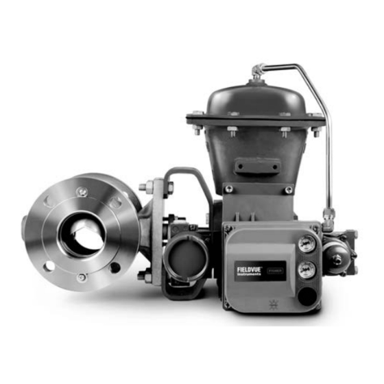
Figure 1. Fisher Vee‐Ball with 2052 Actuator
and FIELDVUE
1
1
2
2
2
3
9
9
11
11
14
20
20
20
24
25
32
32
33
33
39
40
41
X0187
42
Emerson sales office
Vee-Ball Valves
DVC6200 Digital Valve Controller
or Local Business Partner before
June 2017

Advertisement

Table of Contents
loading
Need help?

Need help?

Do you have a question about the Vee-Ball V150 and is the answer not in the manual?

Questions and answers

Subscribe to Our Youtube Channel

Summary of Contents for Fisher Vee-Ball V150

  • Page 1 Introduction Scope of Manual This instruction manual provides installation, operation, maintenance, and parts information for the Fisher Vee‐Ball V150 (NPS 1 through 12), V200 (NPS 1 through 10), and V300 (NPS 1 through 12) rotary control valves (see figure 1).
  • Page 2: Description

    V200 is a flangeless construction. The V150 and V300 valves are raised‐face flanged constructions. The splined valve shaft of all these valves connect to a variety of rotary‐shaft actuators. Specifications Specifications for these valves are shown in table 1 and in the Fisher Vee-Ball V150, V200, and V300 Rotary Control Valves Bulletin 51.3:Vee‐Ball (D101363X012). Educational Services...
  • Page 3: Installation

    Instruction Manual Vee-Ball Valves June 2017 D101554X012 Table 2. Valve Body Materials, End Connections, and Ratings SIZE RATINGS VALVE DESIGN VALVE BODY MATERIAL NPS / DN ASME / PN NPS 1, 1-1/2, 2, 3, 4, 6, 8, 10, 12, 14, 16, 20, 24x20 CL150 DN 80, 100, 150 PN 10-16...
  • Page 4 Figure 2. Flange Stud Length for Seal Protector End DIMENSION SHOWN IN TABLE 3 FIRST FULL THREAD TO FIRST FULL THREAD 1A4520 Table 3. Flange Stud Lengths Required for Seal Protector Ring End of Fisher V150 and V300 Valves V150 V200 V300 VALVE ANSI/ISA S75.08.02...
  • Page 5 Instruction Manual Vee-Ball Valves June 2017 D101554X012 some valve/trim material combinations are limited in their pressure drop and temperature ranges, do not apply any other conditions to the valve without first contacting your Emerson sales office or Local Business Partner. WARNING The valve drive shaft is not necessarily grounded to the pipeline when installed.
  • Page 6 Instruction Manual Vee-Ball Valves June 2017 D101554X012 Installing V150, V300, and Flanged V200 Valves 1. Install the V150 and V300 valve using studs (keys 32 and 33, not shown) and nuts to connect the valve flanges to the pipeline flanges. The seal protector ring (key 3) end of the valve requires longer line flange studs (key 32) than standard.
  • Page 7 Check with your process or safety engineer for any additional measures that must be taken to protect against process media. Figure 4. Fisher V200 Dimensions and Required Clearances for Installation 164 mm (6.44 INCHES) FOR CL150 AND 300 NPS 6 VALVES 12B3060‐L...
  • Page 8 Instruction Manual Vee-Ball Valves June 2017 D101554X012 DIMENSION V200 VALVE Standard CL150 Standard CL150 SIZE, ANSI/ISA ASME B16.10 CL150 ANSI/ISA ASME B16.10 CL300 CL600 S75.08.02 Short (Optional) S75.08.02 Short (Optional) 1-1/2 ‐ ‐ ‐ ‐ ‐ ‐ Inches 4.00 5.00 2.29 6.94 7.94...
  • Page 9: Maintenance

    Instruction Manual Vee-Ball Valves June 2017 D101554X012 Maintenance Valve parts are subject to normal wear and must be inspected and replaced as necessary. The frequency of inspection and replacement depends upon the severity of service conditions. Key numbers in this procedure are shown in figures 24, 25, and 26, unless otherwise noted. WARNING The Vee‐ball closes with a shearing, cutting motion, which could result in personal injury.
  • Page 10 Instruction Manual Vee-Ball Valves June 2017 D101554X012 Disassembly WARNING Observe the steps in the WARNING at the beginning of the Maintenance section. 1. Isolate the control valve from the line pressure, release pressure from both sides of the valve body, and drain the process media from both sides of the valve.
  • Page 11: Replacing The Ball Seal

    Instruction Manual Vee-Ball Valves June 2017 D101554X012 drive shaft or packing box wall; scratching these surfaces could cause leakage. Clean all accessible metal parts and surfaces to remove particles that would prevent the packing from sealing. Assembly If the valve is equipped with the ENVIRO‐SEAL packing system, refer to the ENVIRO‐SEAL Packing System for Rotary Valves instruction manual (D101643X012) for assembly.
  • Page 12 Instruction Manual Vee-Ball Valves June 2017 D101554X012 Figure 5. Packing Arrangements PACKING FOLLOWER (KEY 17) PACKING FOLLOWER (KEY 17) PACKING RING (KEY 35) PACKING SET (KEY 16) PACKING PACKING BOX RING (KEY 39) BOX RING (KEY 39) GRAPHITE RIBBON PACKING PTFE V‐RING PACKING FOR V150, V200, AND V300 FOR V150, V200, AND V300...
  • Page 13 (keys 3 and 15). (For flow ring constructions, go to step 4.) a. For a Fisher TCM seal, remove the seal (key 11) from the valve body. For NPS 1, 1-1/2, and 2 valves, also remove the backup ring (key 14, figure 8) from the valve body.
  • Page 14: Assembly

    Instruction Manual Vee-Ball Valves June 2017 D101554X012 D It might be necessary to remove the HD seal by carefully tapping it with a soft punch and hammer. Take care not to damage the seal protector ring. D NPS 3 through 12 valves, if the seal is difficult to push out, it is recommended that a seal removal plate be used to press the HD seal out of the seal protector ring.
  • Page 15 RADIAL SEAL DRY FILM BACKUP RING (KEY 37) LUBRICANT (KEY 14) WAVE SPRING (KEY 13) HD METAL BALL SEAL (KEY 11) BALL (KEY 48) BALL SEAL BALL (KEY 48) (KEY 11) A6032‐2 Fisher TCM Plus BALL SEAL HD BALL SEAL...
  • Page 16 SPRING SEAL (KEY 13) FLAT METAL BALL SEAL (KEY 11) (KEY 2) NPS 3 THROUGH 12 NPS 3 THROUGH 12 FISHER TCM PLUS SEAL FLAT METAL BALL SEAL RADIAL SEAL (KEY 37) GASKET GASKET WAVE SPRING (KEY 15) (KEY 15)
  • Page 17 10.365‐10.375 Installing Fisher TCM Plus or Extra ball seals: a. NPS 1, 1-1/2, and 2 valves: Install the backup ring (key 14). Install the Fisher TCM seal (key 11) into the valve body. Refer to figure 7. D Install the gasket (key 15) on the valve body.
  • Page 18 Instruction Manual Vee-Ball Valves June 2017 D101554X012 Installing flat metal seals: a. Install 12 shims in the valve and install the flat metal seal on top of the shims. b. Install the spring seal (key 13) on the flat metal seal (key 11) with the convex side of the spring seal facing the ball.
  • Page 19 Instruction Manual Vee-Ball Valves June 2017 D101554X012 b. For all NPS 3 through 8 valves and NPS 10 and 12 valves without attenuator: D Lubricate and install the radial seal (key 37) into the appropriate groove in the seal protector ring making sure the open side of the radial seal faces away from the ball.
  • Page 20: Hd Ball Seal Lubrication

    Instruction Manual Vee-Ball Valves June 2017 D101554X012 c. For NPS 10 and 12 valves: D Place the piston ring (key 133) and retaining ring (key 132) into the appropriate groove in the seal protector ring (key 3). The piston ring has one break in it; do not break it further. D Install the wave spring (key 13) into the seal protector ring (key 3).
  • Page 21 Instruction Manual Vee-Ball Valves June 2017 D101554X012 Disassembly WARNING When the actuator is removed from the valve, the ball/shaft assembly may suddenly rotate, with a shearing, cutting motion, which could result in personal injury. To avoid injury, carefully rotate the ball to a stable position at the bottom of the valve body cavity.
  • Page 22 Instruction Manual Vee-Ball Valves June 2017 D101554X012 9. Thoroughly clean surfaces of all parts that are to be re‐used or obtain replacement parts. Assembly 1. Inspect all sealing surfaces to ensure they are in good condition and without scratches or wear. 2.
  • Page 23 Instruction Manual Vee-Ball Valves June 2017 D101554X012 Table 5. Taper Key Minimum Depth Minimum Depth To Drive Taper Key Valve Size, DN Valve Size, NPS After Initial Solid Contact, mm (Inches) 80, 100, 150 3, 4, 6 4.8 (0.188) 200, 250, 300 8, 10, 12 5.6 (0.219) Table 6.
  • Page 24 Instruction Manual Vee-Ball Valves June 2017 D101554X012 a. Insert the drive shaft into the valve body bearing (key 10), and into the ball ear. Align the hole in the drive shaft with the holes in the ball. b. Insert the taper key into the ball and drive shaft as shown in figure 14. D Installing the Taper Key Current standard construction materials for all NPS 3 through 12 valves require the taper key (key 4, figure 14) to be tack welded in place after properly seating, using the following procedure.
  • Page 25 Instruction Manual Vee-Ball Valves June 2017 D101554X012 12. Inspect the ball/shaft taper key connection to verify that the taper key spans the entire shaft flat width. If not, the taper key must be driven in further until this condition is satisfied. However, do not exceed the maximum depths shown in table 6.
  • Page 26 Instruction Manual Vee-Ball Valves June 2017 D101554X012 Key numbers in this procedure are shown in figures 24, 25, and 26, unless otherwise indicated. 1. A taper pin (key 4, figure 20) is used in the NPS 1, 1-1/2, and 2 valves, and in the NPS 1 Metal Micro‐Notch valve (figure 21).
  • Page 27 Instruction Manual Vee-Ball Valves June 2017 D101554X012 5. Working from the small end of the groove pin (key 7), use a pin punch to drive the groove pin out of the ball ear and follower shaft. Note All NPS 1 Micro‐Notch constructions use a one piece shaft. They do not have a follower shaft. 6.
  • Page 28 Instruction Manual Vee-Ball Valves June 2017 D101554X012 8. Make sure the sealing surface of the ball is not damaged while removing the follower shaft. a. If a pipe plug (key 25) is installed, use a punch to drive the follower shaft (key 9) into the center of the ball. b.
  • Page 29 Instruction Manual Vee-Ball Valves June 2017 D101554X012 Carefully install the ball into the valve body cavity. After you have installed the ball (key 2) into the valve body assembly, firmly support the ball while installing the shafts. 4. Installing the follower shaft (key 9): D For NPS 1 through 2 valves: The follower shaft (key 9) should already have been inserted into the ball before the ball was put into the valve body.
  • Page 30 Instruction Manual Vee-Ball Valves June 2017 D101554X012 6. Insert the drive shaft into the valve body bearing (key 10), and into the ball ear (or ball, for Micro‐Notch constructions). Align the hole in the drive shaft with the holes in the ball. Note There is an indicator hole drilled in all Micro‐Notch balls.
  • Page 31 TAPER PIN (KEY 6) (KEY 4) BALL (KEY 2) A6033‐1 Figure 21. Taper Pin Installation for Fisher V150, V200, and V300 NPS 1 Valves with Micro‐Notch Ball Construction WHEN FULLY SET, PIN ± SHOULD BE FLUSH OR 0.06' DRIVE SHAFT (KEY 6) MICRO‐NOTCH BALL...
  • Page 32: Actuator Mounting

    Instruction Manual Vee-Ball Valves June 2017 D101554X012 Note There is an indicator hole drilled in all Micro‐Notch balls. The orientation of this hole in the ceramic Vee‐Ball is to the right of the screw in the ball, and must be located closest to the follower end of the ball/shaft assembly. See figures 19 and 22. WARNING Avoid personal injury and property damage from ignition of process fluid caused by sparks from ceramic trim.
  • Page 33: Determining Closed Position

    Instruction Manual Vee-Ball Valves June 2017 D101554X012 The NPS 1 through 2 has two notches, and can be rotated in either direction. Determining Closed Position 1. The valve must be removed from the line to check the position of the ball. WARNING The Vee‐Ball closes with a shearing, cutting motion.
  • Page 34 Instruction Manual Vee-Ball Valves June 2017 D101554X012 Figure 23. Index Marks for Actuator Lever Orientation for NPS 1 through 12 Valves with or without Attenuator NOTE: 1. ARROW ON LEVER INDICATES DIRECTION OF ACTUATOR THRUST TO CLOSE VALVE. 2. THE OPTIONAL LEFT-HAND ORIENTATION IS NOT AVAILABLE FOR MICRO-NOTCH VEE-BALLS. 48B4773‐C...
  • Page 35 Instruction Manual Vee-Ball Valves June 2017 D101554X012 Figure 24. Fisher V150 or V300 (NPS 3 - 12) or Flanged V200 (NPS 3 - 8) Valve Assembly (Details are typical for V200 Flangeless valve body) LEAKOFF ALLOY NPS 10 & 12...
  • Page 36 Instruction Manual Vee-Ball Valves June 2017 D101554X012 Figure 25. Exploded View, Fisher V150 and V300 (NPS 3 - 12) and Flanged V200 (NPS 3-8) without Attenuator Assembly.
  • Page 37 Instruction Manual Vee-Ball Valves June 2017 D101554X012 Figure 26. Fisher V150 or V300 (NPS 1, 1-1/2, and 2) and Flanged V200 (NPS 2) Valve Assembly (Details are typical for Flangeless V200) ALLOY ASSEMBLY TCM SEAL PIPE PLUG OPTIONAL NOTE: PARTS NOT SHOWN: 30, 31, 32, 33, 35 & 36...
  • Page 38 Instruction Manual Vee-Ball Valves June 2017 D101554X012 Figure 27. Centering Template in Use and Template Dimensions 19B8493 19B8493 E0740 E0741 VALVE SIZE, VALVE SIZE, ANSI/ISA (FOR ASME VALVES) (FOR DIN VALVES) (ASME B16.10 Short S75.08.02 1-1/2 Inches 2.50 2.68 0.75 1.40 2.40 1.00...
  • Page 39: Parts Ordering

    Use only genuine Fisher replacement parts. Components that are not supplied by Emerson Automation Solutions should not, under any circumstances, be used in any Fisher valve, because they will void your warranty, might adversely affect the performance of the valve, and could give rise to personal injury and property damage.
  • Page 40: Parts Kits

    2. Included in key 105. Repair Kits for Ball Seals Seal repair kits include recommended spare parts for Fisher TCM Plus, S31600 stainless steel, CF10SMnN, or CD7MCuN ball seal constructions. The following table indicates the repair kit part number and the quantity of parts included in the kit.
  • Page 41: Parts List

     Silver‐plated R30016 (alloy 6B)  316L SST Nitride  Carbon‐filled PTFE with N10276 sleeve Description  Glass‐filled PTFE with N10276 sleeve  11* Ball Seal Packing Flange Stud  Fisher TCM Plus Packing Flange Nut  Fisher TCM Ultra Packing Flange    Flat Metal Spring Pack Assembly   S31600...
  • Page 42: Appendix A Instructions For Non‐Series B

    Instruction Manual Vee-Ball Valves June 2017 D101554X012 Appendix A Instructions for Non‐Series B The Series B changes affected only the NPS 3 through 12 valves without attenuators. To determine if a Vee‐Ball valve is Series B, you will need to examine several of the internal parts. Compare the distinctive skirted V‐notch outline of the forward side and the circular edge on the reverse side of the Series B design ball to the V‐notch on both sides of the non‐series B design ball.
  • Page 43 Instruction Manual Vee-Ball Valves June 2017 D101554X012 Key numbers in this procedure are shown in figures 24, 26, and 30, unless otherwise indicated. A taper key (key 4, figure 14) is used in NPS 3 through 12 Non‐Series B valves. 3.
  • Page 44 Instruction Manual Vee-Ball Valves June 2017 D101554X012 Assembly 1. Inspect all sealing surfaces to ensure they are in good condition and without scratches or wear. 2. Installing bearings (key 10): a. For composition bearings, install the bearings by hand. The bearing flanged end should touch the bushing (key 5 or 8).
  • Page 45 Instruction Manual Vee-Ball Valves June 2017 D101554X012 Failure to use the correct Vee‐Ball/ shaft combination may result in the ball not being in the position indicated by the slash mark on the end of the shaft. If the ball is not properly aligned with the slash mark, the valve will not function correctly and seal damage may result.
  • Page 46: Determining Mounting Position

    Instruction Manual Vee-Ball Valves June 2017 D101554X012 D 3/16 inch diameter weld on NPS 8 through 10 valves, and D 1/4 inch diameter weld on NPS 12 valves. For all constructions: Refer to Replacing the Ball Seal, Packing Maintenance, and other procedures as necessary to complete the assembly of the valve.
  • Page 47 Use only genuine Fisher replacement parts. Components that are not supplied by Emerson Automation Solutions should not, under any circumstances, be used in any Fisher valve, because they will void your warranty, might adversely affect the performance of the valve, and could give rise to personal injury and property damage.
  • Page 48 Instruction Manual Vee-Ball Valves June 2017 D101554X012 BEARING RAM DIMENSIONS BUSHING RAM DIMENSIONS VALVE Ram Lengths Ram Diameters Ram Diameters SIZE, Long Ram d Short Ram d Inches Inches Inches Inches Inches Inches Inches 201.42 7.930 95.25 3.750 22.86 0.900 19.05 0.750 28.19...
  • Page 49 Instruction Manual Vee-Ball Valves June 2017 D101554X012 Figure 30. Fisher V150 and V300 Non‐Series B Valve Assembly (NPS 3- 12) (Details are typical for V200 Valves except V200 does not have flanges) METAL BEARING METAL PEEK BEARING NPS 3‐6 BEARING NPS 8, 10, &...
  • Page 50 Instruction Manual Vee-Ball Valves June 2017 D101554X012 Figure 31. Index Marks for Actuator Lever Orientation for Non‐Series B Valves ACTUATOR ACTUATOR POSITION VALVE OPEN MOUNTING STYLE STYLE A (PDTC) RIGHT‐ HAND STYLE B (PDTO) STYLE C (PDTC) LEFT‐ HAND STYLE D (PDTO) 1.
  • Page 51 Instruction Manual Vee-Ball Valves June 2017 D101554X012...
  • Page 52 Responsibility for proper selection, use, and maintenance of any product remains solely with the purchaser and end user. Fisher, ENVIRO-SEAL, Vee-Ball, and FIELDVUE are marks owned by one of the companies in the Emerson Automation Solutions business unit of Emerson Electric Co.

This manual is also suitable for:

Vee-ball v200Vee-ball v300

Table of Contents

Save PDF