Table of Contents
Advertisement
Instruction Manual
D103042X012
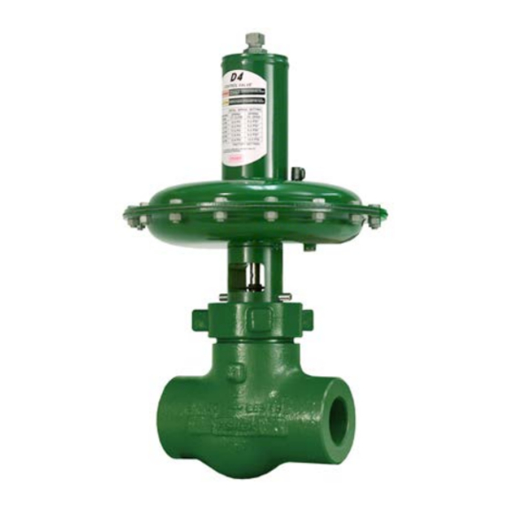
Fisherr D4 Control Valve Assembly
Contents
. . . . . . . . . . . . . . . . . . . . . . . . . . . . . . . . .
. . . . . . . . . . . . . . . . . . . . . . . . . . . . .
. . . . . . . . . . . . . . . . . . . . . . . . . . . . . . . . .
. . . . . . . . . . . . . . . . . . . . . . . . . . . . . . .
. . . . . . . . . . . . . . . . . . . . . . . . .
. . . . . . . . . . . . . . . . . . . . . . . . . . . . . . . . . .
. . . . . . . . . . . . . . . . . . . . . . . . . . . .
. . . . . . . . . . . . . . . . . . . . . . . . . . . . . . . . .
. . . . . . . . . . . . . . . . . . . . . . . . . . . . . . .
. . . . . . . . . . . . . . . . . . . . . . . . . . . . . . . . . .
. . . . . . . . . . . . . . . . . . . . . . . . . . . . . . .
. . . . . . . . . . . . . . . . . . . . . . . . . . . . . . . . . .
. . . . . . . . . . . . . . . . . . . . . . . . . . . . . . . . . . .
. . . . . . . . . . . . . . . . . . . . . . . . . . . . . . . . .
Introduction
Scope of Manual
This instruction manual provides installation, maintenance, and parts information for the Fisher D4 control valve.
Do not install, operate, or maintain a D4 control valve without being fully trained and qualified in valve, actuator, and
accessory installation, operation, and maintenance. To avoid personal injury or property damage, it is important to
carefully read, understand, and follow all the contents of this manual, including all safety cautions and warnings. If you
have any questions about these instructions, contact your
proceeding.
Description
The D4 control valve is a compact, rugged valve designed primarily for high-pressure throttling applications. This valve
is ideal for use on pressure and flow control applications within the oil and gas production industry. The D4 valve also
makes an excellent dump valve for high-pressure separators and scrubbers.
The D4 control valve meets the metallurgical requirements of NACE MR0175/ISO 15156 without environmental limits
for temperatures below 135_C (275_F). If the temperature is above 135_C (275_F), the N07718 Belleville washers will
impose some limits, as shown in table 3.
www.Fisher.com
. . . . . . . . . . . . . . . . . . . . . .
Figure 1. Fisher D4 Control Valve
1
1
1
2
2
4
5
6
6
8
10
13
14
14
17
W8531
Emerson Process Management sales office
D4 Valve
July 2015
before
Advertisement
Table of Contents

Related Manuals for Fisher D4


Summary of Contents for Fisher D4
-
Page 1: Table Of Contents
The D4 control valve is a compact, rugged valve designed primarily for high‐pressure throttling applications. This valve is ideal for use on pressure and flow control applications within the oil and gas production industry. The D4 valve also makes an excellent dump valve for high‐pressure separators and scrubbers. -
Page 2: Specifications
1. The pressure or temperature limits in the referenced tables and any applicable ASME code limitations should not be exceeded. Specifications Table 1 lists specifications for the D4 control valve. Some of the specifications for a given control valve as it originally comes from the factory are stamped on a nameplate located on the actuator spring barrel. - Page 3 CL1500 CL1500 0.25, 0.375, 0.5, 0.75 0.25, 0.375, 0.5 0.75, 1, 1.25 X = Available construction. Table 3. D4 Environmental Limits for NACE MR0175/ISO 15156 with Sour Trim MAXIMUM TEMPERATURE MAXIMUM H S PARTIAL PRESSURE COMPATIBLE WITH ELEMENTAL SULFUR? psia No Limit Table 4.
-
Page 4: Installation
Instruction Manual D4 Valve July 2015 D103042X012 Table 6. Maximum Shutoff Pressure Drops for Fisher D4 Control Valves (Spring‐to‐Open) When Used with Typical Control Instrumentation INPUT SIGNAL TO 0 to 1.2 Bar 0 to 1.4 Bar 0 to 2.0 Bar 0 to 2.3 Bar... -
Page 5: Spring Adjustment
Instruction Manual D4 Valve D103042X012 July 2015 WARNING When ordered, the valve configuration and construction materials were selected to meet particular pressure, temperature, pressure drop, and controlled fluid conditions. Responsibility for the safety of process media and compatibility of valve materials with process media rests solely with the purchaser and end‐user. -
Page 6: Maintenance
Valve Plug and Seat Ring The D4 control valve is designed to allow easy access to the valve plug and seat ring without disturbing the packing. Refer to other sections of this instruction manual if additional maintenance is required. - Page 7 Instruction Manual D4 Valve D103042X012 July 2015 Disassembly 1. Remove the loading pressure tubing and any accessories that may hamper disassembly. 2. Break the hammer nut (key 6) loose with a hammer. Continue turning the hammer nut by using a hammer or a large adjustable wrench, tightened around one ear of the hammer nut.
-
Page 8: Valve Packing
These instructions apply to valves manufactured with serial numbers equal to and greater than 18679262. See Appendix A for information on packing constructions with serial numbers less than 18679262. If your D4 valve assembly has a packing retainer lock ring (see figure 6), proceed to Appendix A. WARNING Observe the warning at the start of the Maintenance section. - Page 9 Instruction Manual D4 Valve D103042X012 July 2015 Figure 2. Fisher D4 Packing Installation UPPER PACKING SPACER (KEY 48) UNTIGHTENED, FULLY TIGHTENED, NOTE THE GAP NO GAP PACKING RETAINER (KEY 8) BELLEVILLE SPRINGS FULLY ENCLOSED BY VALVE PLUG, BELLEVILLE SPRINGS, AND PACKING RETAINER...
-
Page 10: Actuator
PVC pipe. 3. Remove the packing spacer from the packing bore. CAUTION All D4 packing kits include a single use packet of high performance fluorinated grease. This is the only acceptable D4 packing lubricant. Note In the following procedure, carefully install each packing ring individually over the valve stem and push completely into the packing box with a non‐marring tube. - Page 11 Instruction Manual D4 Valve D103042X012 July 2015 Before disassembling the actuator, disassemble the valve plug, seat ring, and packing according to instructions in this manual. Disassembly 1. Loosen the adjusting screw nut (key 44) and turn the adjusting screw (key 31) counterclockwise to remove all spring compression.
- Page 12 Instruction Manual D4 Valve July 2015 D103042X012 is against the O‐ring (key 25). Also, make sure that it is assembled for installation with the diaphragm on the loading pressure side and the lockwasher (key 43) and lower spring seat (key 28) are on the spring side.
-
Page 13: Parts Ordering
8. Adjust the initial spring set per the Spring Adjustment section in this manual. Parts Ordering Each D4 control valve is assigned a serial number, which can be found on the nameplate. Refer to the number when contacting your Emerson Process Management sales office... -
Page 14: Repair Kits
Use only genuine Fisher replacement parts. Components that are not supplied by Emerson Process Management should not, under any circumstances, be used in any Fisher valve, because they may void your warranty, might adversely affect the performance of the valve, and could cause personal injury and property damage. -
Page 15: D103042X012 July
Instruction Manual D4 Valve D103042X012 July 2015 Figure 4. Fisher D4 Valve Assembly (Spring‐to‐Close) BELLEVILLE SPRING AND PACKING ARRANGEMENT GE02332‐C APPLY LUB... - Page 16 Instruction Manual D4 Valve July 2015 D103042X012 Figure 5. Fisher D4 Valve Assembly (Spring‐to‐Open) BELLEVILLE SPRING AND PACKING ARRANGEMENT GE02334‐E APPLY LUB...
-
Page 17: Appendix A
Instruction Manual D4 Valve D103042X012 July 2015 Appendix A Note These instructions apply to valves manufactured with serial numbers less than 18679262. Valve Packing WARNING Observe the warning at the start of the Maintenance section. The valve stem packing can only be accessed from within the valve body. If packing maintenance is required, first disassemble per steps 1, 2, and 6 or 7 in the Valve Plug and Seat Ring Disassembly section of this document. - Page 18 Instruction Manual D4 Valve July 2015 D103042X012 Figure 6. Fisher D4 Belleville Spring Procedure PACKING RETAINER LOCK RING (KEY 22) BELLEVILLE SPRINGS REASONABLY TIGHT BELLEVILLE SPRINGS FINGER TIGHT, THEN TIGHTEN TO SEAT THE PACKING 1/2 TURN (3 FLATS ON THE RETAINER)
- Page 19 PVC pipe. 3. Remove the packing spacer from the packing bore. CAUTION All D4 packing kits include a single use packet of high performance fluorinated grease. This is the only acceptable D4 packing lubricant. Note In the following procedure, carefully install each packing ring individually over the valve stem and push completely into the packing box with a non‐marring tube.
- Page 20 Responsibility for proper selection, use, and maintenance of any product remains solely with the purchaser and end user. Fisher is a mark owned by one of the companies in the Emerson Process Management business unit of Emerson Electric Co. Emerson Process Management, Emerson, and the Emerson logo are trademarks and service marks of Emerson Electric Co.
Need help?
Do you have a question about the D4 and is the answer not in the manual?
Questions and answers