Table of Contents
Advertisement
Available languages
Available languages
IMPORTANT:
Read Before Using
Operating/Safety Instructions
Consignes de fonctionnement/sécurité
Instrucciones de funcionamiento
y seguridad
1594
Renseignement des consommateurs
Toll Free Number:
1-877-BOSCH99 (1-877-267-2499) http://www.boschtools.com
For English
See page 2
IMPORTANT :
Lire avant usage
Consumer Information
Información para el consumidor
Appel gratuit :
Parlez-vous français?
Voir page 15
IMPORTANTE:
Leer antes de usar
Número de teléfono gratuito:
¿Habla español?
Ver página 28
Advertisement
Table of Contents

Related Manuals for Bosch 1594


Summary of Contents for Bosch 1594
- Page 1 IMPORTANT: IMPORTANT : Read Before Using Lire avant usage Operating/Safety Instructions Consignes de fonctionnement/sécurité Instrucciones de funcionamiento y seguridad 1594 Consumer Information Renseignement des consommateurs Información para el consumidor Toll Free Number: Appel gratuit : 1-877-BOSCH99 (1-877-267-2499) http://www.boschtools.com For English Parlez-vous français?
-
Page 2: Power Tool Safety Rules
Power Tool Safety Rules Read and understand all instructions. Failure to follow all instructions listed WARNING below, may result in electric shock, fire and/or serious personal injury. SAVE THESE INSTRUCTIONS Work Area Keep your work area clean and well lit. Cluttered benches and dark areas invite accidents. - Page 3 Do not force tool. Use the correct tool for your application. The correct tool will do the job better and safer at the rate for which it is designed. Do not use tool if switch does not turn it “ON” or “OFF”. Any tool that cannot be controlled with the switch is dangerous and must be repaired.
- Page 4 Always hold the tool firmly with both hands for maximum control. Never pull the plane backward over the workpiece. Loss of control may occur. Do not put fingers or any objects into the chip ejector or clean out chips while tool is running.
- Page 5 MPORTANT: Some of the following symbols may be used on your tool. Please study them and learn their meaning. Proper interpretation of these symbols will allow you to operate the tool better and safer. Symbol Name Volts Amperes Hertz Watt Kilograms Minutes Seconds...
-
Page 6: Functional Description And Specifications
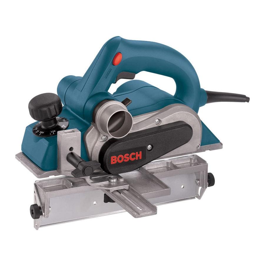
RABBETING DEPTH STOP (OPTIONAL) FRONT SHOE CHAMFER V-GROOVES DEPTH SCALE Note: Each unlabeled mark represents 0.5 mm. Model number 1594 Voltage rating 120 V 50 - 60Hz Amperage rating 6.5 A No load speed 16,500/min Planer “LOCK-OFF” RELEASE BUTTON PORT SELECTOR LEVER... -
Page 7: Chip Extraction
Henceforth, all references in this manual to “mini TC blades” refer to both Woodrazor blades and standard mini tungsten carbide blades. • To use large HSS blades with the 1594 it is necessary to purchase optional accessories. Wear protective gloves... -
Page 8: Installation Procedure
4. Rotate the blade drum 180° and repeat the procedure to remove the second blade. INSTALLING AND ADJUSTING MINI CARBIDE BLADES If the blades and/or holder are gummed and difficult to remove, remove the clamping jaws and screws and clean all surfaces with mineral spirits;... - Page 9 CONVERSION TO HIGH-SPEED STEEL BLADES The 1594 Planer can be converted to accept large HSS blades. The conversion requires the optional PA1204 HSS Blades with Retainers (pair). (Fig. 7) Additional pairs of HSS blade, the PA1205 large HSS blades, can also be purchased separately.
- Page 10 RESHARPENING HSS BLADES Worn or dull HSS plane blades can be re- sharpened. The optimal blade angle of 50º should be maintained when sharpening. Once a total of 6 mm of steel has been removed from tips of the blades, both blades must be replaced because the minimum HSS blade height is 23 mm from back to tip.
-
Page 11: Operating Instructions
Operating Instructions TRIGGER "ON/OFF" SWITCH Hold the tool with both WARNING hands while starting the tool, since torque from the motor can cause the tool to twist. To turn tool "ON": depress the “Lock-Off” release button from either side and squeeze the trigger switch. - Page 12 PARK REST STAND The park rest stand automatically springs down to help keep the blade from coming in contact with the work surface when planer is not in use (Fig. 11). The park rest stand is designed to swing up and out of the way by it itself when the back of the plane crosses the leading edge of the workpiece (Fig.
-
Page 13: Drive Belt
STRAIGHT GUIDE FENCE The optional Straight Guide Fence can be used to cut various desired widths. (Fig. 14) Installing the guide fence: Place the wing knob through the appropriate hole in the guide bracket and screw into the housing. Securely tighten wing knob. Setting the cutting width: Loosen wing knob and slide the fence along the guide bracket to the desired position. -
Page 14: Tool Lubrication
Service Preventive maintenance WARNING performed by unauthorized personnel may result in misplacing of internal wires and components which could cause serious hazard. recommend that all tool service be performed by a Bosch Factory Service Center or Autho- rized Bosch Service Station. TOOL LUBRICATION Your Bosch tool has been properly lubricated and is ready to use. -
Page 15: Règles De Sécurité Générales
Règles de Sécurité Générales Vous devez lire et comprendre toutes les instructions. Len on-respect, même partiel, AVERTISSEMENT des instructions ci-après entraîne un risque de choc életrique, d'incendie et/ou de blessures graves. CONSERVEZ CES INSTRUCTIONS Aire de travail Veillez à ce que l'aire de travail soit propre et bien éclairée. - Page 16 Ne forcez pas l'outil. Utilisez l'outil approprié à la tâche. L'outil correct fonctionne mieux et de façon plus sécuritaire. Respectez aussi la vitesse de travail qui lui est propre. N'utilisez pas un outil si son interrupteur est bloqué. Un outil que vous ne pouvez pas commander par son interrupteur est dangereux et doit être réparé.
- Page 17 Tenez toujours l’outil fermement à deux mains pour mieux le maîtriser. Ne tirez jamais le rabot vers l’arrière sur la surface de la pièce. Vous risquez d’en perdre le contrôle. Ne mettez pas les doigts ou tout autre objet dans la buse d’évacuation des copeaux.
- Page 18 IMPORTANT : Certains des symboles suivants peuvent être utilisés sur votre outil. Veuillez les étudier et apprendre leur signification. Une interprétation appropriée de ces symboles vous permettra d'utiliser l'outil de façon plus efficace et plus sûre. Symbole Volts Ampères Hertz Watt Kilogrammes Minutes...
-
Page 19: Description Fonctionnelle Et Spécifications
SEMELLE AVANT GORGE EN VÉ POUR CHANFREINER INCLINABLE ÉCHELLE PROFONDEUR Remarque : les graduations sans repères correspondent à 0,5 mm. Numéro de modèle 1594 Tension nominale 120 V 50 - 60Hz Intensité nominale 6.5 A Régime à vide 16,500/min Rabot SUR ARRÊT... - Page 20 (livré en standard avec le rabot électrique Bosch 1594), et les grands fers en acier rapide. • Bien que les mini fers Bosch 1594 au carbure de tungstène soient plus tranchants et plus durables que les mini fers ordinaires au carbure de tungstène, l’assemblage et le réglage se font de la...
- Page 21 INSTALLATION ET RÉGLAGE DES MINI-FERS AU CARBURE Si les fers ou les porte-fers sont encrassés et que les fers sont difficiles à enlever, ôtez les mâchoires et les vis de bridage et nettoyez toutes les surfaces avec du white spirit, du dissolvant à vernis ou de l’alcool. Ceci permettra de régler correctement le fer et améliorera la performance de l’outil.
- Page 22 CONVERSION POUR L’UTILISATION DE FERS EN ACIER RAPIDE Le rabot 1594 peut être converti pour utiliser des grands fers en acier rapide. La conversion nécessite des fers en acier rapide PA1204 avec des contre-fers (paire) disponibles en option (Fig. 7).
- Page 23 RAFFÛTAGE DES FERS EN ACIER RAPIDE Les fers en acier rapide usés ou émoussés peuvent être raffûtés. L’angle de coupe optimal est de 50°. Il convient de le respecter lors de l’affûtage. Une fois qu’un total de 6 mm d’acier a été enlevé des arêtes des fers, les deux fers doivent être remplacés car la cote minimale des fers en acier rapide est de 23 mm de la face arrière à...
-
Page 24: Instructions D'utilisation
Instructions d’utilisation INTERRUPTEUR MARCHE/ARRÊT À GÂCHETTE Tenez l’outil à deux mains AVERTISSEMENT quand vous le démarrez car le couple du moteur risque de le faire pivoter. Pour mettre l’outil en marche, enfoncez le bouton de verrouillage sur arrêt dans un sens ou dans l’autre et appuyez sur l’interrupteur à... - Page 25 REPOSOIR Le reposoir pivote automatiquement vers le bas pour empêcher le fer de toucher la surface de la pièce quand on n’utilise pas le rabot (Fig. 11). Le reposoir est conçu pour pivoter vers le haut automatiquement et dégager quand l’arrière du rabot passe au niveau de l’extrémité...
- Page 26 GUIDE DE LARGEUR PARALLÈLE Le guide de largeur parallèle en option permet de raboter à des largeurs variées (Fig. 14) Montage du guide : Enfilez le bouton à ailettes dans le trou du support de guide approprié et vissez-le dans le carter. Serrez fermement le bouton à ailette. Réglage de la largeur de rabotage : Desserrez le bouton à...
-
Page 27: Entretien
Service Tout entretien préventif AVERTISSEMENT effectué personnels non autorisés peut résulter en mauvais placement de fils internes ou de pièces, ce qui peut présenter un danger grave. Nous vous conseillons de faire faire tout l’entretien par un centre de service d’usine Bosch ou une station service agréée Bosch. - Page 28 Normas de seguridad para herramientas mecánicas Lea y entienda todas las instrucciones. El incumplimiento de todas las instrucciones ADVERTENCIA indicadas a continuación puede dar lugar a sacudidas eléctricas, incendios y/o lesiones personales graves. CONSERVE ESTAS INSTRUCCIONES Area de trabajo Mantenga el área de trabajo limpia y bien iluminada.
- Page 29 Utilización y cuidado de las herramientas Utilice abrazaderas u otro modo práctico de fijar y soportar la pieza de trabajo a una plataforma estable. La sujeción de la pieza de trabajo con la mano o contra el cuerpo resulta inestable y puede ocasionar pérdida de control.
- Page 30 golpear la carcasa de la herramienta y dañar la herramienta, así como causar posibles lesiones. Sujete siempre firmemente la herramienta con las dos manos para tener un control máximo. Nunca tire del cepillo mecánico hacia atrás sobre la pieza de trabajo. Podría producirse pérdida de control.
- Page 31 IMPORTANTE: Es posible que algunos de los símbolos siguientes se usen en su herramienta. Por favor, estúdielos y aprenda su significado. La interpretación adecuada de estos símbolos le permitirá utilizar la herramienta mejor y con más seguridad. Símbolo Nombre Volt Ampere Hertz Watt...
-
Page 32: Descripción Funcional Y Especificaciones
RANURA EN V DE ACHAFLANAR TOPE-GUÍA DE PIVOTE ESCALA PROFUNDIDAD Nota: Cada marca sin número representa 0.5 mm. Número de modelo 1594 Tensión nominal 120 V 50 - 60Hz Amperaje nominal 6.5 A Capacidad sin carga 18 000/min BOTÓN DE FIJACIÓN... - Page 33 Bosch (equipo estándar con el cepillo mecánico Bosch 1594) y cuchillas de AAV grandes. • Aunque las minicuchillas de carburo de tungsteno Bosch 1594 son más afiladas y más duraderas que las minicuchillas de carburo de tungsteno estándar, el ensamblaje y el ajuste de las cuchillas de carburo de tungsteno tanto Woodrazor como estándar son iguales.
- Page 34 4. Gire el tambor de las cuchillas 180° y repita el procedimiento para quitar la segunda cuchilla. INSTALACIÓN Y AJUSTE DE LAS MINICUCHILLAS DE CARBURO Si las cuchillas y/o el portacuchilla están gomosos y son difíciles de quitar, quite las mandíbulas de fijación y los tornillos de fijación y limpie todas las superficies con alcoholes minerales, diluyente de laca o alcohol, ya que esto asegurará...
- Page 35 A CUCHILLAS DE ACERO DE ALTA VELOCIDAD El cepillo mecánico 1594 puede convertirse para aceptar cuchillas de AAV grandes. La conversión requiere las cuchillas de AAV PA1204 opcionales con retenedores (par). (Fig. 7.) También pueden comprarse por separado pares adicionales de cuchillas de AAV y las cuchillas de AAV grandes PA1205.
- Page 36 REAFILADO DE LAS CUCHILLAS DE AAV Las cuchillas de AVV de cepillo mecánico desgastadas o desafiladas pueden reafilarse. El ángulo óptimo de 50° de la cuchilla debe mantenerse al reafilar la cuchilla. Una vez que se haya quitado un total de 6 mm de acero de las puntas de las cuchillas, ambas cuchillas deben reemplazarse, porque la altura mínima de la cuchilla de AAV es de 23 mm desde la parte trasera...
-
Page 37: Instrucciones De Funcionamiento
Instrucciones de funcionamiento INTERRUPTOR GATILLO DE ENCENDIDO Y APAGADO Sujete la herramienta con las ADVERTENCIA dos manos mientras la pone en marcha, ya que el par de fuerzas del motor puede hacer que la herramienta se tuerza. Para encender la herramienta: oprima el botón de "Fijación en apagado"... - Page 38 BASE DE APOYO DE ESTACIONAMIENTO La base de apoyo de estacionamiento baja automáticamente por resorte para ayudar a evitar que la cuchilla entre en contacto con la superficie de la pieza de trabajo cuando no se esté utilizando el cepillo mecánico (Fig.
- Page 39 TOPE-GUÍA DE ANCHURA PARALELO El tope-guía de anchura paralelo opcional puede utilizarse para cortar diversos anchos deseados. (Fig. 14.) Instalación del tope-guía: Coloque el pomo de mariposa a través del agujero apropiado del soporte de guía y enrósquelo en la carcasa. Apriete firmemente el pomo de mariposa.
-
Page 40: Mantenimiento
Servicio El mantenimiento preventivo ADVERTENCIA realizado por personal no autorizado pude dar lugar a la colocación incorrecta de cables y componentes internos que podría constituir un peligro serio. Recomendamos que todo el servicio de las herramientas sea realizado por un Centro de servicio de fábrica Bosch o por una Estación de servicio Bosch autorizada. - Page 41 -41-...
- Page 42 -42-...
- Page 43 -43-...
- Page 44 LIMITED WARRANTY OF BOSCH PORTABLE AND BENCHTOP POWER TOOLS Robert Bosch Tool Corporation (“Seller”) warrants to the original purchaser only, that all BOSCH portable and benchtop power tools will be free from defects in material or workmanship for a period of one year from date of purchase. SELLER’S SOLE OBLIGATION AND YOUR EXCLUSIVE REMEDY under this Limited Warranty and, to the extent permitted by law, any warranty or condition implied by law, shall be the repair or replacement of parts, without charge, which are defective in material or workmanship and which have not been misused, carelessly handled, or misrepaired by persons other than Seller or Authorized Service Station.
Need help?
Do you have a question about the 1594 and is the answer not in the manual?
Questions and answers