CONTENTS 1. Preface 2. Specifications 2.1 Performance Data of Swimming Pool Heat Pump Unit 2.2 Dimensions for Swimming Pool Heat Pump Unit 3. Installation and Connection 3.1 Installation of System 3.2 Swimming Pool Heat Pumps Location 3.3 How Close to Your Pool? 3.4 Swimming Pool Heat Pumps Plumbing 3.5 Swimming Pool Heat Pumps Electrical Wiring 3.6 Initial Start-up of the Unit...
1. PREFACE In order to provide our customers with quality, reliability and versatility, this product has been made to strict production standards. This manual includes all the necessary information about installa- tion, debugging, discharging and maintenance. Please read this manual carefully before you open or maintain the unit.
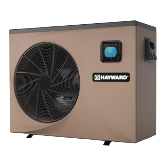
2.SPECIFICATION 2.1 Performance data of Swimming Pool Heat Pump Unit REFRIGERANT : R410A UNIT Model HP50AEE HP70AEE Rated Heating Power Input 2.68 3.86 Range 0.2-2.68 0.31-3.86 Rated Running Current Input 12.0 16.9 Range 1.1-12.0 1.5-16.9 Power Supply V/Hz 208-230V~/60Hz 208-230V~/60Hz...
2.SPECIFICATION 2.2 The dimensions for Swimming Pool Heat Pump Unit unit:mm/in HP50AEE 1048/ 41.2 1002/ 39.4 water outlet 1.5’’ 350/ 13.8 water inlet 1.5’’ 610/ 24.0 104/4.1 HP70AEE 1165/ 45.9 1115/ 43.9 water outlet 1.5’’ 400/ 15.7 water inlet 1.5’’...
3.INSTALLATION AND CONNECTION 3.1 Installation illustration Valve Chlorinator cell Water outlet Water supply Pool Water inlet Sand filter Water pump (or other type filter) Installation items: The factory only provides the main unit and the water unit; the other items in the illustration are necessary spare parts for the water system ,that provided by users or the installer.
3.INSTALLATION AND CONNECTION 3.2 Swimming Pool Heat Pumps Location The unit will perform well in any outdoor location provided that the following three factors are presented: 1. Fresh Air - 2. Electricity - 3. Pool filter piping The unit may be installed virtually anywhere outdoors. For indoor pools please consult the supplier. Unlike a gas heater, it has no draft or pilot light problem in a windy area.
3.INSTALLATION AND CONNECTION 3.4 Swimming Pool Heat Pumps Plumbing The Swimming Pool Heat Pumps exclusive rated flow titanium heat exchanger requires no special plumbing arrangements except bypass(please set the flow rate according to the nameplate). The water pressure drop is less than 10kPa at max. Flow rate. Since there is no residual heat or flame Tempera- tures, The unit does not need copper heat sink piping.
3.INSTALLATION AND CONNECTION 3.5 Swimming Pool Heat Pumps Electrical Wiring NOTE: Although the unit heat exchanger is electrically isolated from the rest of the unit, it simply prevents the flow of electricity to or from the pool water. Grounding the unit is still required to protect you against short circuits inside the unit.
4. USAGE 4.1. Color screen wire controller interface introduction 4.1.1 Main interface Shutdown status Booting status Inlet water ° ℃ ℃ Time Temp Seting Outlet Water Time t in Water Time ℃ ℃ ℃ ℃ ° 07 00 28.5 18.5 °...
Page 12
4. USAGE 4.1.2 Button and display Description Name Description Time Show the system time Temp. Setting Show the target temperature Outlet Water Show the outlet water temperature Inlet Water Show the inlet water temperature ON/OFF or Back Press to control the unit ON/OFF,or back to the previous interface Defrost icon The icon will display when the unit working on defrost mode Mode...
4. USAGE 4.2. Color screen wire controller function introduction 4.2.1 Booting and shutdown In the main interface: 1) In shutdown status, press the ON/OFF button for 0.5s then the unit will be booted. 2) In booting status, press the ON/OFF button for 0.5s then the unit will be shut down. press button Inlet water “...
Page 14
4. USAGE 4.2.4 Target temperature setting In the Second function interface,click “ ” to enter into the Temp Setting interface, slide up or down to select the target temperature, click “OK” to save the setting and back to the previous interface;...
Page 15
4. USAGE 4.2.6 Timing settings In the Third function interface,click “ ” to enter into the Time setting interface, click the value of “ON” to enter into the Start time selecting interface, slide up or down to adjust the value, click “OK” to save (click “...
Page 16
4. USAGE 4.2.7 Silent Mode and silent timing (1) Silent Mode In the Second function interface,click “ ” to active the Silent Mode, the icon show “ ”, click the icon again the Silent Mode function can be off. click “ ”...
Page 17
4. USAGE 4.2.8 The fault interface When fault occus, the fault icon “ ” will display in the main interface. To check the fault record list, slide to the Third function interface, click “ ” to enter into the Fault history record interface, click “...
5. MAINTENANCE AND INSPECTION (2) Parameter list Meaning Default Remarks 27ഒ Refrigeration target temperature set point Ajustable Ajustable Heating the target temperature set point 27ഒ Ajustable 27ഒ Automatic target temerature set point 5. Maintenance and inspection Check the water supply device and the release often. You should avoid the condition of no water or air entering into system, as this will influence unit's performance and reliability.
6.APPENDIX 6.1 Connection of PCB illustration (1) Wire control interface diagram and definition Sign Meaning 12V power + No use No use 485A 485B GND(power-) (2) Controller interface diagram and definition...
Page 22
6.APPENDIX Connections explanation᧶ Symbol Meaning OUT1 Compressor ( output 220-230VAC) OUT2 Water pump ( output 220-230VAC) OUT3 4-way valve ( output 220-230VAC) OUT4 High speed of fan ( output 220-230VAC) OUT5 Low speed of fan (output 220-230VAC) AC-L Live wire ( input 220-230VAC) AC-N Neutral wire ( input 220-230VAC)...
HP12˖High pressure protection(4.4MPa) IT˖Inlet water temperature AT CT OT IT SUT LP FS 3 4 5 6 HP11 KM1˖Contactor of high pressure K2˖Relay of pump COMP LP˖Low pressure protection OT˖Outlet water temperature SUT˖Suction temperature Remote 4V˖4 way valve ON/OFF HP50AEE/ HP70AEE CODE˖20181023-0001...
Page 25
6.APPENDIX Spare Parts List Specifications Code Name 301090-20120001 Front box 20000-230596 Trademark 250X55 72200070 CP203 82300038 + 82400012 20000-220369 Fan net 20000-270004 Axial fan blade Z500-145 20000-330132 ZWS75-A 32012-120166 Finned heat exchanger 680x290x700x¢7x1.5 2.0 301070-20080006 Back network Galvanized sheet 32012-210570 Motor bracket black 9005 32012-210493...
Page 27
6.APPENDIX Spare Parts List Specifications Code Name 301090-00000004 Front box 20000-230596 Trademark 250X55 72200070 CP203 82300038 + 82400012 20000-220369 Fan net 20000-270004 Axial fan blade Z500-145 20000-330132 ZWS75-A 80701595 Back network Galvanized sheet 301060-20180001 Finned heat exchanger 714x353x800x¢7x2 2.0 32009-210663 Support plate Galvanized sheet 1.5 black 9005 80900216...
Need help?
Do you have a question about the HP50AEE and is the answer not in the manual?
Questions and answers