Advertisement
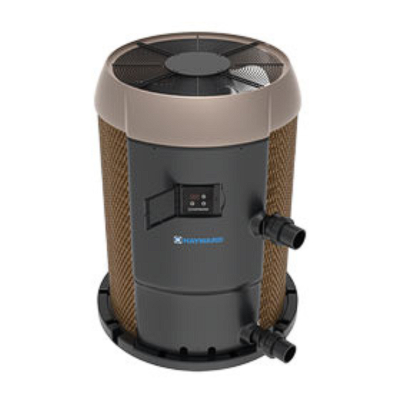
Hayward HeatPro Heat Pump
Pool Water Heat Pump with Cooling
Installation and Operation Manual
HP31005T
Hayward Industries
1415 Vantage Park Dr., Suite 400
Charlotte, NC 28203
Phone: (908) 355-7995
www.hayward.com
USE ONLY HAYWARD GENUINE REPLACEMENT PARTS
Contents
Safety Instructions...............1
Getting Started....................2
Installation........................10
Operation..........................17
Maintenance & Service......25
Troubleshooting................27
51300056501 RevG
Advertisement

Related Manuals for Hayward HeatPro HP31005T


Summary of Contents for Hayward HeatPro HP31005T
-
Page 1: Table Of Contents
Pool Water Heat Pump with Cooling Installation and Operation Manual Contents Safety Instructions....1 Getting Started....2 Installation......10 Operation......17 Maintenance & Service..25 Troubleshooting....27 HP31005T Hayward Industries 1415 Vantage Park Dr., Suite 400 Charlotte, NC 28203 Phone: (908) 355-7995 www.hayward.com USE ONLY HAYWARD GENUINE REPLACEMENT PARTS... -
Page 2: Safety Instructions
National Electric Code (NEC) in the United States and the Canadian Electric Code (CEC) in Canada. This product must be installed and serviced by authorized personnel, qualified in pool/spa heater installation. Improper installation and/or operation can cause serious injury, property damage, or death. SAVE THESE INSTRUCTIONS USE ONLY HAYWARD GENUINE REPLACEMENT PARTS... -
Page 3: Getting Started
Verify Chlorine or Bromine level ever 2-3 days • Verify pH level every week • Verify Alkalinity level every 3-4 weeks (2 weeks if using an automatic feeder) • Verify Water Hardness and Total Dissolved Solids every month • USE ONLY HAYWARD GENUINE REPLACEMENT PARTS... - Page 4 WARNING: To avoid possible outer jacket damage or injury: (1) no materials should be stored against the jacket and (2) care should be taken to avoid unnec- essary contact (especially by children) with the jacket. See product rating plate for manufactures information. Place Installation Notes Here: Model: Serial Number: Date of Installation: Installation Company: USE ONLY HAYWARD GENUINE REPLACEMENT PARTS...
- Page 5 HEATER CONSTRUCTION Names of heat pump heater components: Figure1: Sub-Assemblies Fan Top Evaporator Control Box Control Box Compressor Cover Separator Front Panel Condenser Display USE ONLY HAYWARD GENUINE REPLACEMENT PARTS...
- Page 6 Unit size L x W x H (in) 36.2 x 33.8 x 44.2 Weight (lbs) Shipping Weight (lbs) Shipping size L x W x H (in) 32 x 32 x 46.0 31.5” (80cm) 40” (101cm) 18.9” (47cm) 4.2” (10cm) USE ONLY HAYWARD GENUINE REPLACEMENT PARTS...
- Page 7 208-230 VAC : Red 1 2 3 4 : Blue : Green Y BK 208-230 VAC HET / REMOTE : Gray : Yellow ON/OFF Low Voltage : Orange HP70HA2 240/203 VAC, 60 Hz, 1 Ph USE ONLY HAYWARD GENUINE REPLACEMENT PARTS...
- Page 8 To reduce risk of injury, do not permit children to use or climb on this product. Closely supervise children at all times. Components such as the filtration system, pumps, and heaters must be positioned to prevent children from using them as a means of access to the pool. USE ONLY HAYWARD GENUINE REPLACEMENT PARTS...
- Page 9 Do not tamper with controls, because scalding can result if safety controls are not in proper working order. USE ONLY HAYWARD GENUINE REPLACEMENT PARTS...
- Page 10 Pounds per square inch (PSI) is typically used with water “pressure”, “suction” or system measurements. Inches of Water (inwc) is typically used with gas or air pressure measurements (1.0 inHg = .49 PSI = 13.5inwc) USE ONLY HAYWARD GENUINE REPLACEMENT PARTS...
-
Page 11: Installation
NOTICE - DO NOT install the heat pump in a fully enclosed space (i.e. garage, shed etc.). Such an installation will void its warranty. All criteria given in the following sections reflect minimum clearances. However, each installation must also be evaluated on prevailing local conditions such as proximity and height of walls and public access areas. USE ONLY HAYWARD GENUINE REPLACEMENT PARTS... - Page 12 Testing has shown this heat pump can be installed as close as 6” (to coil) from a restriction (Wall, Fence, etc.). USE ONLY HAYWARD GENUINE REPLACEMENT PARTS...
- Page 13 Failure to install an External Bypass Assembly with a flow rate of 75 GPM or higher will void the warranty. Do not install any restriction in the water pipe between the heater outlet and the pool with the exception of; three-way switching valve, in-line chlorinator and/or chlorinator check valve as shown in Figure 5. USE ONLY HAYWARD GENUINE REPLACEMENT PARTS...
- Page 14 Gasket Union Union Gasket USE ONLY HAYWARD GENUINE REPLACEMENT PARTS USE ONLY HAYWARD GENUINE REPLACEMENT PARTS...
- Page 15 Refer to LOCATING THE HEATER section for more details. Install bypass loops for each unit. Install union style fittings from the heat pump CONSUMER KIT adjacent to the unit to facilitate easy service procedures Pool (Parallel) USE ONLY HAYWARD GENUINE REPLACEMENT PARTS USE ONLY HAYWARD GENUINE REPLACEMENT PARTS...
- Page 16 The power connections are to be made on the contactor terminals located in the control box (see Figure10 Power Connections). Plug any unused openings with the sup- plied caps. USE ONLY HAYWARD GENUINE REPLACEMENT PARTS...
- Page 17 30 ft) for the connection from the Omni control to the HP31005T. Route the cable through appropriate knockouts making sure they are not shared with high voltage wiring. Refer to the diagram below showing a Hayward OmniLogic control wired to the heat pump. Note that the position of each colored conductor is the same at both ends of the communication cable.
-
Page 18: Operation
Refrigerant (A) is throttled by Metering Device (TXV) and turned into low temperature, low-pressure saturated liquid (B). The two-phase Refrigerant flows through the Air Coil (Evaporator), where the liquid refrigerant evaporates into vapor by absorbing heat from the surrounding air. At the outlet of the Air Coil USE ONLY HAYWARD GENUINE REPLACEMENT PARTS... - Page 19 When the unit is off, press the ON/OFF key and hold on for 0.5 seconds to turn on the unit; When the unit is on, press the ON/OFF key and hold on for 0.5 seconds to turn off the unit. 0.5s Heater Off - Main Interface Heater On - Main Interface (Actual water temp. displayed) USE ONLY HAYWARD GENUINE REPLACEMENT PARTS...
- Page 20 Cooling Mode: The unit will turn on whenever the actual water temperature rises above the target temperature. Auto Mode: The unit will turn on whenever the actual water temperature drops below OR rises above the target temperature. USE ONLY HAYWARD GENUINE REPLACEMENT PARTS...
- Page 21 Connect the thermostat cable to the “Remote On/Off” terminal. After the thermostat cable is fastened and secure, refasten the panels. Follow the steps on the next page to enable bypass operation. USE ONLY HAYWARD GENUINE REPLACEMENT PARTS...
- Page 22 Use the UP and DOWN keys to select the parameter “b”. Press and hold the UP and DOWN keys for 1 second to enter the bypass operation setting interface. User Setting Interface Bypass Operation Setting Interface (Parameter “b” selected) USE ONLY HAYWARD GENUINE REPLACEMENT PARTS...
- Page 23 NOTE: If a fault occurs, the error code will be displayed on the heater interface and no opera- tions can be performed. If the fault is cleared, the heater interface will return to the “rC” display. Remote Control Interface (Only displayed when connected to an Omni Control system) USE ONLY HAYWARD GENUINE REPLACEMENT PARTS...
- Page 24 After changing the setting values, wait 5 seconds for the unit to save the settings and return to the clock setting interface. Use the UP and DOWN keys to select the next clock or timer setting that you would like to adjust until you are finished. USE ONLY HAYWARD GENUINE REPLACEMENT PARTS...
- Page 25 AI/DIO7 Water output temperature (input) CN12 Program port AI/DIO8 Coil 1 temperature (input) CN13 Centralized control communication port Wire Control Interface Definition Sign Meaning 485B 485A 12V (power +) Communication signal GND (power -) USE ONLY HAYWARD GENUINE REPLACEMENT PARTS...
-
Page 26: Maintenance & Service
Use a 4-way pool/spa water test kit to check your water frequently (at least weekly). Use the following guidelines to help maintain proper water chemistry. USE ONLY HAYWARD GENUINE REPLACEMENT PARTS... - Page 27 Always disconnect power circuit before connecting the heat pump, or working on the heat pump. This equipment contains wiring that carries high voltage. Contact with these wires could result in death or personal injury and/or may also cause property damage. USE ONLY HAYWARD GENUINE REPLACEMENT PARTS...
-
Page 28: Troubleshooting
Turn the unit off for several hours, but leave the filter pump running bottom of unit Possible water leak continuously. If water quantity decreases, then it is only condensation. Otherwise there is a possible leak. USE ONLY HAYWARD GENUINE REPLACEMENT PARTS... - Page 29 1. Install a new fan motor Fan Motor 2 Fault 2. Wire connection between DC fan motor module 2. Check the wire connection and make sure they are and fan motor is in bad contact in good contact USE ONLY HAYWARD GENUINE REPLACEMENT PARTS...
- Page 30 Check and adjust the current EEPROM Overcurrent Warning MCU error Check if the chip is damaged and replace if necessary V15V Over/Undervoltage Fault V15V is overloaded or undervoltage Check the V15V input voltage (range: 13.5V to 16.5V) USE ONLY HAYWARD GENUINE REPLACEMENT PARTS...
- Page 31 Notes USE ONLY HAYWARD GENUINE REPLACEMENT PARTS...
- Page 32 All other trademarks not owned by Hayward are the property of their respective owners. Hayward is not in any way affiliated with or endorsed by those third parties. For patent information, refer to www.hayward.com/patents. USE ONLY HAYWARD GENUINE REPLACEMENT PARTS...
Need help?
Do you have a question about the HeatPro HP31005T and is the answer not in the manual?
Questions and answers