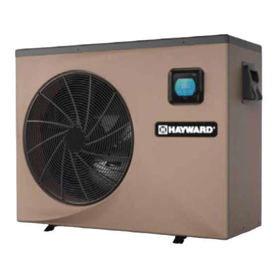
Table of Contents
Advertisement
Quick Links
- 1 Performance Data of Swimming Pool Heat Pump Unit
- 2 Specifications
- 3 Installation of System
- 4 Swimming Pool Heat Pumps Electrical Wiring
- 5 Initial Startup of the Unit
- 6 Color Screen Wire Controller Interface Introduction
- 7 Usage and Operation
- 8 Parameter List and Breakdown Table
- Download this manual
Advertisement
Table of Contents

Summarization of Contents
2. SPECIFICATIONS
2.1 Performance Data of Swimming Pool Heat Pump Unit
Details performance specifications including refrigerant, power, current, and noise levels.
2.2 Dimensions for Swimming Pool Heat Pump Unit
Provides detailed physical measurements for HP50AEE and HP70AEE models.
3. INSTALLATION AND CONNECTION
3.1 Installation Illustration
Illustrates the basic plumbing setup for the heat pump system.
3.2 Swimming Pool Heat Pumps Location
Discusses ideal outdoor placement, ventilation, and required clearances.
3.3 How Close to Your Pool?
Advises on optimal distance from the pool to minimize heat loss.
3.4 Swimming Pool Heat Pumps Plumbing
Details pipe connections, types, and condensation drainage for the system.
3.5 Swimming Pool Heat Pumps Electrical Wiring
Explains hookup, grounding, bonding, and disconnect requirements.
3.6 Initial Start-up of the Unit
Provides a step-by-step guide for the first-time operation after installation.
4. USAGE
4.1. Color screen wire controller interface introduction
Introduces the main and function screens of the digital control panel.
4.1.2 Button and display Description
Lists and describes the function of each button and display element on the controller.
4.2. Color screen wire controller function introduction
Explains how to navigate and operate the controller's various functions.
4.2.1 Booting and shutdown
Details the procedure for turning the unit on and off using the controller.
4.2.2 Function selection interface
Describes how to switch between different operational modes and settings on the controller.
4.2.3 Mode switch
Guides on selecting between heating, cooling, or auto operational modes.
4.2.4 Target temperature setting
Explains how to adjust the desired water temperature for the pool.
4.2.5 System time setting
Details the procedure for setting the unit's internal date and time.
4.2.6 Timing settings
Guides on configuring ON/OFF timers for automated unit operation.
4.2.7 Silent Mode and silent timing
Explains how to activate silent mode and schedule its operation.
4.2.8 The fault interface
Describes how to view, interpret, and clear fault codes and error messages.
4.2.8 Keyboard locking
Explains the procedure for locking and unlocking the controller screen.
4.3 Parameter list and breakdown table
Lists fault codes, reasons, and elimination methods.
4.3.1 Electronic control fault table
Details electronic control faults, their display, reasons, and solutions.
4.3.2 Frequency conversion board fault table
Lists faults related to the frequency conversion board and their remedies.
5. MAINTENANCE AND INSPECTION
(2) Parameter list
Lists default and adjustable operational parameters for the unit.
5. Maintenance and inspection
Provides essential guidelines for regular maintenance and inspection of the unit.
6.APPENDIX
6.1 Connection of PCB illustration
Shows wiring diagrams for wire control and controller interfaces.
(1) Wire control interface diagram and definition
Defines the signals and connections for the wire control interface.
(2) Controller interface diagram and definition
Defines the signals and connections for the main controller interface.
Connections explanation
Explains the function of each connection symbol in a detailed table.
6.2 Wiring Diagram
Presents the overall electrical wiring diagram for the heat pump system.
6.3 Exploded View - HP50AEE
Illustrates the assembly and electrical components of the HP50AEE model.
(1) Complete machine structure explosion diagram
Illustrates the physical assembly of the HP50AEE unit components.
(2) Electrical control structure explosion diagram
Details the arrangement of electrical components within the HP50AEE.
(3) Spare Parts List
Lists all available spare parts with codes, names, and specifications for HP50AEE.
6.3 Exploded View - HP70AEE
Illustrates the assembly and electrical components of the HP70AEE model.
(1) Complete machine structure explosion diagram
Illustrates the physical assembly of the HP70AEE unit components.
(2) Electrical control structure explosion diagram
Details the arrangement of electrical components within the HP70AEE.
(3) Spare Parts List
Lists all available spare parts with codes, names, and specifications for HP70AEE.


Need help?
Do you have a question about the HP70AEE and is the answer not in the manual?
Questions and answers