
Related Manuals for Estun Summa Series


Summary of Contents for Estun Summa Series
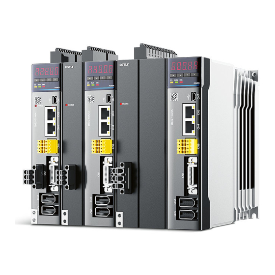
- Page 1 2019 Summa Series Servodrive Product Manual Drive Model: ED3S ESTUN AUTOMATION CO.,LTD.
-
Page 2: Terms
This manual provides the information required for the Selection, Wiring, Connection, Settings, Trial Operation, Tuning and Functions of the Summa Series AC Servo Drive (referred to as ED3S). Read and understand this manual to ensure correct usage of the product. -
Page 3: Symbols
The Value is b0000 Parameter Pn000 Press [◄] key Pn000.0 = 0 Pn000.1 = 0 Pn000.2 = 0 Pn000.3 = 0 Document Version: V1.01 © 2019 ESTUN Automation Co., Ltd. All right reserved. (Dec, 2019) -
Page 4: Safety Precautions
Use a Noise Filter to minimize the effects of electromagnetic interference. Always use a Motor and Drive in one of the specified combinations. Never touch a Drive or Motor with wet hands. Document Version: V1.01 © 2019 ESTUN Automation Co., Ltd. All right reserved. (Dec, 2019) -
Page 5: Storage Precautions
Install the Drive in the specified orientation. Provide the specified clearances between the Drive and the control cabinet as well as with other devices. Document Version: V1.01 © 2019 ESTUN Automation Co., Ltd. All right reserved. (Dec, 2019) -
Page 6: Wiring Precautions
When replacing the Drive, transfer the user parameters from the WARNING replaced Drive to new Drive. Never change the wiring while the power is on. Never disassemble the Motor without permission. Document Version: V1.01 © 2019 ESTUN Automation Co., Ltd. All right reserved. (Dec, 2019) -
Page 7: Disposal Precautions
When disposing of the product, treat it as ordinary industrial waste. However, local ordinances and national laws must be observed. Implement all labeling and warnings as a final product as required. Document Version: V1.01 © 2019 ESTUN Automation Co., Ltd. All right reserved. (Dec, 2019) -
Page 8: Table Of Contents
Operation Precautions ............................. v Maintenance Precautions ..........................v Disposal Precautions ............................vi Contents .............................. i Chapter 1 Summa Series AC Drive ................... 1-1 1.1 Product Features............................. 1-1 1.2 Interpreting the Nameplate........................1-2 1.3 Model Designations ..........................1-2 1.4 Part Names ............................. 1-3 1.5 Ratings and Specifications ........................ - Page 9 6.7.2 Cyclic Synchronous Torque (CST) Mode ..................6-71 6.8 Torque Limits ............................6-73 6.9 Digital and Remote I/O Signals ......................6-74 6.10 Touch Probe ............................6-75 Document Version: V1.01 © 2019 ESTUN Automation Co., Ltd. All right reserved. (Dec, 2019)
- Page 10 Chapter 9 Tuning .......................... 9-1 9.1 Overview ..............................9-1 9.1.1 Basic Conception..........................9-1 9.1.2 Control Block Diagram ........................9-2 9.1.3 Tuning Process ..........................9-3 9.1.4 Precautions Before Tuning ....................... 9-4 Document Version: V1.01 © 2019 ESTUN Automation Co., Ltd. All right reserved. (Dec, 2019)
- Page 11 12.1.1 Interpreting the Parameter Lists ....................12-1 12.1.2 Parameters Detailed ........................12-2 12.2 Alarms Displays ..........................12-30 12.3 Object Dictionary ..........................12-36 12.3.1 General Objects .......................... 12-36 Document Version: V1.01 © 2019 ESTUN Automation Co., Ltd. All right reserved. (Dec, 2019)
- Page 12 12.3.11 Profile Torque / Cyclic Synchronous Torque Mode ..............12-62 12.3.12 Torque Limit Function ......................12-63 12.3.13 Digital Inputs/Outputs ......................12-64 12.3.14 Object Dictionary List ......................12-65 Document Version: V1.01 © 2019 ESTUN Automation Co., Ltd. All right reserved. (Dec, 2019)
-
Page 13: Chapter 1 Summa Series Ac Drive
Chapter 1 Summa Series AC Drive 1.1 Product Features ED3S is ESTUN's newly developed single-axis AC Servo Drive, which is designed in an array, supports close installation and flexible common DC bus structure, suitable for large machinery applications. Its excellent performance, with EtherCAT protocol, can achieve the motion control of High-Speed, High- Precision, High-Safety, and maximize the performance of the machine in the shortest possible time. -
Page 14: Interpreting The Nameplate
1 kW Interface and Options 1.5 kW EtherCAT 2 kW EtherCAT, STO, Fully-closed 3 kW NOTE: Specifications marked with an asterisk (*) have not been released yet. Document Version: V1.01 © 2019 ESTUN Automation Co., Ltd. All right reserved. (Dec, 2019) -
Page 15: Part Names
The connection terminals for the control power supply Main Circuit Terminals The connection terminals for the main circuit power supply Motor Terminals The connection terminals for the Motor main circuit cable Document Version: V1.01 © 2019 ESTUN Automation Co., Ltd. All right reserved. (Dec, 2019) -
Page 16: Ratings And Specifications
Protection Class IP20 Environmental Altitude 1,000 m or less Conditions Vibration 4.9m/s Resistance Shock Resistance 19.6m/s Power System TN System Mounting Base-mounted Speed Control Performance 1:5000 Range Document Version: V1.01 © 2019 ESTUN Automation Co., Ltd. All right reserved. (Dec, 2019) - Page 17 Process Data Assignments can be changed with PDO mapping. Emergency messages, SDO requests, SDO responses, and SDO information MailBox (CoE) (TxPDO/RxPDO and remote TxPDO/RxPDO are not supported.) Document Version: V1.01 © 2019 ESTUN Automation Co., Ltd. All right reserved. (Dec, 2019)
- Page 18 Supports A, B, and Z TTL differential type sensor signal [NOTE]: when using single-phase AC power for ED3S-15A* drivers, reduce the load factor rating to 80%. Document Version: V1.01 © 2019 ESTUN Automation Co., Ltd. All right reserved. (Dec, 2019)
-
Page 19: External Dimensions
(75) 2×M4 Mounting Hole Diagram ED3S-20* to ED3S-30* 3 × M4 Unit: mm Exterior 85±0.5 (mounting pitch) Grounding terminals (75) 2 x M4 Mounting Hole Diagram Document Version: V1.01 © 2019 ESTUN Automation Co., Ltd. All right reserved. (Dec, 2019) -
Page 20: System Configuration
ED3S-08A*, -10A*: 25Ω resistor between B1 and B2. ED3S-15A*, -20A*, -30A*: 10Ω (1): ED3S-A5*, ED3S-01*, ED3S-02* and ED3S-04* must connect an external regenerative resistor. Document Version: V1.01 © 2019 ESTUN Automation Co., Ltd. All right reserved. (Dec, 2019) -
Page 21: Chapter 2 Installation
Drive and mount it securely in the mounting holes (The number of mounting holes depends on the capacity of the Drive). Figure 2-1 Base-mounted diagram Base Airflow Document Version: V1.01 © 2019 ESTUN Automation Co., Ltd. All right reserved. (Dec, 2019) -
Page 22: Mounting Hole Dimensions
Figure 2-2 Install one Drive in a control cabinet Mounting ≥ 50mm Wiring allowance plate ≥30mm ≥75mm ≥30mm ≥50mm Mounting allowance between mounting plate and cabinet shall be not less than 6.4 mm Document Version: V1.01 © 2019 ESTUN Automation Co., Ltd. All right reserved. (Dec, 2019) - Page 23 Figure 2-3 Install more than one Drive in a control cabinet ≥50mm ≥30mm ≥30mm ≥50mm The ED3S Drivers can be mounted closely and the distance between adjacent Drives is 1mm. Document Version: V1.01 © 2019 ESTUN Automation Co., Ltd. All right reserved. (Dec, 2019)
-
Page 24: Emc Installation Conditions
The EMC installation conditions that are given here are the conditions that were used to pass testing criteria at ESTUN. The EMC level may change under other conditions, such as the actual installation structure and wiring conditions. These ESTUN products are designed to be built into equipment. -
Page 25: Ferrite Coil Mounting
It is recommended that you deploy your system as described above. ESTUN is not responsible for the risk of electromagnetic interference caused by the above-mentioned setups not being used on your application. -
Page 26: Chapter 3 Wiring And Connecting
Install molded-case circuit breakers and other safety measures to provide protection against short circuits in external wiring. Document Version: V1.01 © 2019 ESTUN Automation Co., Ltd. All right reserved. (Dec, 2019) -
Page 27: Countermeasures Against Noise
Refer to the section Noise Filters for information on connecting Noise Filters. Implement suitable grounding measures. Refer to the section 3.1.3 Grounding for information on grounding measures. Document Version: V1.01 © 2019 ESTUN Automation Co., Ltd. All right reserved. (Dec, 2019) - Page 28 Separate input lines from output lines. Do not place input lines and output lines in the same duct or bundle them together. Noise Filter Noise Filter Ground Ground plate plate Document Version: V1.01 © 2019 ESTUN Automation Co., Ltd. All right reserved. (Dec, 2019)
- Page 29 Connect the Noise Filter ground wire directly to the grounding plate. Do not connect the Noise Filter ground wire to other ground wires. Noise Filter Noise Filter Drive Drive Drive Drive Shielded ground wire Ground Ground plate plate Document Version: V1.01 © 2019 ESTUN Automation Co., Ltd. All right reserved. (Dec, 2019)
-
Page 30: Grounding
If the Motor Main Circuit Cable is placed in a metal conduit, ground the conduit and its junction box. For all grounding, ground at one point only. Document Version: V1.01 © 2019 ESTUN Automation Co., Ltd. All right reserved. (Dec, 2019) -
Page 31: Basic Wiring Diagrams
ALM-RST Anode connection method. PAO+ PAO- 4.7 kΩ +24V IN EXT1 PBO+ PBO- EXT2 PCO+ PCO- Switch Safety Fuse HWBB1+ Terminals HWBB1- EDM+ HWBB2+ EDM- HWBB2- Document Version: V1.01 © 2019 ESTUN Automation Co., Ltd. All right reserved. (Dec, 2019) -
Page 32: Wiring The Power Supply To Drive
For the common DC bus, connect all P2 of Drive to the positive pole, and N to the negative pole. Ground terminal Always connect this terminal to prevent electric shock. Document Version: V1.01 © 2019 ESTUN Automation Co., Ltd. All right reserved. (Dec, 2019) -
Page 33: Wiring Procedure
Insert the cable into the ferrule (It should protrude 1 mm or more from the ferrule). Figure 3-4 Insert the cable into the ferrule 1 mm or more Document Version: V1.01 © 2019 ESTUN Automation Co., Ltd. All right reserved. (Dec, 2019) - Page 34 Step 8 When you have completed wiring, attach connection terminals to the Drive. The above wiring procedure is also applicable to the Motor Terminals. Document Version: V1.01 © 2019 ESTUN Automation Co., Ltd. All right reserved. (Dec, 2019)
-
Page 35: Wiring Diagrams
SA[1] D[1]: Flywheel Diode KM[1] KM[2] Ry[1] KM[1] SA[2] [NOTE]: when using single-phase AC power for ED3S-15A* drivers, reduce the load factor rating to 80%. Document Version: V1.01 © 2019 ESTUN Automation Co., Ltd. All right reserved. 3-10 (Dec, 2019) - Page 36 (for control power supply) KM[2]: Magnetic Contactor 2 (for main circuit power supply) SA[1] Ry[1]: Relay KM[1] KM[2] PL[1]: Indicator Lamp D[1]: Flywheel Diode Ry[1] KM[1] SA[2] Document Version: V1.01 © 2019 ESTUN Automation Co., Ltd. All right reserved. 3-11 (Dec, 2019)
-
Page 37: Wiring The Motor
Gray Black Yellow-Green White Motor connection side Green Symbols Color Terminal without brake Brown Gray Black Yellow-Green Symbols Color Brown Drive connection side Gray Black Document Version: V1.01 © 2019 ESTUN Automation Co., Ltd. All right reserved. 3-12 (Dec, 2019) -
Page 38: Wiring The Encoder
Terminals Arrangement Terminals Pin Layout Symbols Color Blue Blue-Black Ordinary Plug BAT+ Yellow Green Motor connection side Green-Black PG5V PG0V Black BAT- Yellow-Black Frame ground Document Version: V1.01 © 2019 ESTUN Automation Co., Ltd. All right reserved. 3-13 (Dec, 2019) - Page 39 Keep the Control power supply to the Drive is ON when you remove the battery case or disconnect the Encoder Cable, in case losing the absolute encoder data. Prepare the following items before connecting a Battery Case. Document Version: V1.01 © 2019 ESTUN Automation Co., Ltd. All right reserved. 3-14 (Dec, 2019)
- Page 40 Guide Rail 4. Insert the terminals of the Battery Case into the connector. The reverse installation procedure is the disassembling procedure of the battery case. Document Version: V1.01 © 2019 ESTUN Automation Co., Ltd. All right reserved. 3-15 (Dec, 2019)
-
Page 41: I/O Signal Connections
Positioning Completion signal indicates that Motor positioning has been completed during position control. COIN- Output Alarm Reset Input signal can reset the servo alarm and ALM-RST Input continue operation. Document Version: V1.01 © 2019 ESTUN Automation Co., Ltd. All right reserved. 3-16 (Dec, 2019) -
Page 42: Communication Connections
Connect to the next Drive's IN The OUT of the last drive can be optionally connected to other valid devices, such as IO modules. Document Version: V1.01 © 2019 ESTUN Automation Co., Ltd. All right reserved. 3-17 (Dec, 2019) - Page 43 Use category 5e Ethernet communications cables to make the connections, and metal shielded terminals are recommended to prevent signal interference. Metal shielded are recommended Use category 5e Ethernet communications cables Document Version: V1.01 © 2019 ESTUN Automation Co., Ltd. All right reserved. 3-18 (Dec, 2019)
-
Page 44: Usb Communication Cable
PC Cable Description You can purchase the USB Communication Cable provided by ESTUN, or you can purchase the commercially available products yourself. The plug connected to your PC is USB Type-A, and the plug connected to the Drive is Mini USB Type-B. -
Page 45: Wiring The External Encoder
3.9 Connecting STO Function Signals A Safety Function Device shall be connected for using the STO function. For the connection and usage, please refers to Chapter 11STO. Document Version: V1.01 © 2019 ESTUN Automation Co., Ltd. All right reserved. 3-20 (Dec, 2019) -
Page 46: Chapter 4 Basic Settings
Press [▼] Key to decrease the set value. Data setting key ◀ To display parameter setting and set value. To shift to the next digit on the left. Document Version: V1.01 © 2019 ESTUN Automation Co., Ltd. All right reserved. (Dec, 2019) -
Page 47: Basic Mode Selection
The display meaning of each segment on Bit Data are shown in Table 4-1, and they have different meanings under Speed or Torque Control Mode and Position Control Mode. Document Version: V1.01 © 2019 ESTUN Automation Co., Ltd. All right reserved. (Dec, 2019) - Page 48 Meaning Servo initialization failed (check the encoder connection) Servo OFF (Motor Power OFF) Servo Ready Servo ON (Motor Power ON) Quick Stop State Servo Alarm State Document Version: V1.01 © 2019 ESTUN Automation Co., Ltd. All right reserved. (Dec, 2019)
-
Page 49: Parameter Setting Mode
Press and hold [◄] key for 1 second or more, and then a flashing decimal point will appear at the bottom Step 4 right of the 5th digit. Decimal point is flashing Document Version: V1.01 © 2019 ESTUN Automation Co., Ltd. All right reserved. (Dec, 2019) - Page 50 Press and hold [▲] key or [▼] key to jump the setting value quickly. Press [◄] key or [M] key to return to the display of Pn102. Step 5 Document Version: V1.01 © 2019 ESTUN Automation Co., Ltd. All right reserved. (Dec, 2019)
- Page 51 Press and hold [◄] key for 1 second or more to return to the display of the Pn504 parameter value, or Step 9 press the [M] key to return to the display of the Pn504. Document Version: V1.01 © 2019 ESTUN Automation Co., Ltd. All right reserved. (Dec, 2019)
-
Page 52: Monitor Mode
Input reference pulse counter 1 pulse - Un010 Reserved Un011 Pulse deviation counter 1 pulse - Un012 Reserved Un013 Reference pulse 1 pulse - Un014 Reserved Document Version: V1.01 © 2019 ESTUN Automation Co., Ltd. All right reserved. (Dec, 2019) -
Page 53: Utility Function Mode
This section describes how to apply the basic operations using the Panel Operator to run and adjust the Motor. The following table shows the parameters in the Utility Function Mode. Function Number Name Fn000 Alarm trace data display Fn001 Initialize parameter settings Document Version: V1.01 © 2019 ESTUN Automation Co., Ltd. All right reserved. (Dec, 2019) - Page 54 Manual offset-adjustment of Motor current detection signal Fn007 Software version display Fn009 Load inertia identification Fn010 Absolute encoder multi-turn reset Fn011 Absolute encoder alarm reset Fn017 Auto-tuning tool Fn018 PJOG operation Document Version: V1.01 © 2019 ESTUN Automation Co., Ltd. All right reserved. (Dec, 2019)
- Page 55 Press [▲] key or [▼] key to select the function number Fn001. Step 2 Press [◄] key, and Panel Operator displays as below. Step 3 Document Version: V1.01 © 2019 ESTUN Automation Co., Ltd. All right reserved. 4-10 (Dec, 2019)
- Page 56 This utility function often use used for trial operation, refers to the section 8.3.3 JOG Operation. Fn005 (Automatic offset-adjustment of Motor current detection signal) Motor current detection offset adjustment has performed at ESTUN before shipping. Basically, the user need not perform this adjustment.
- Page 57 Press and hold [◄] key for 1 second or more to return to the phase display. Step 7 Press [◄] key to return to the display of the Fn006. Step 8 Document Version: V1.01 © 2019 ESTUN Automation Co., Ltd. All right reserved. 4-12 (Dec, 2019)
- Page 58 Press [◄] key to return to the display of the Fn007. Step 5 Fn009 (Load inertia identification) This utility function often use used for tuning, refers to the section 9.7.1 Load Inertia Identification. Document Version: V1.01 © 2019 ESTUN Automation Co., Ltd. All right reserved. 4-13 (Dec, 2019)
- Page 59 This utility function often use used for tuning, refers to the section 9.3.1 Auto-Tuning Tool. Fn018 (PJOG operation) This utility function often use used for trial operation, refers to the section 8.5 Program Jogging. Document Version: V1.01 © 2019 ESTUN Automation Co., Ltd. All right reserved. 4-14 (Dec, 2019)
-
Page 60: Esview V4
Visit ESTUN official website www.estun.com to find and download ESView V4 on Technical Support > Download for getting the compressed file. For help, please contact ESTUN. Turn on the power supply of PC and start Windows. (Close down other software running.) ... - Page 61 Step 4 An exclamatory mark attaches to the option Other devices > ESTUN USB COMM in Device Manager window, which indicates an error occurs in the driver and needs to update, as shown in Figure 4-4. Document Version: V1.01 ©...
- Page 62 Basic Settings Figure 4-4 An error occurs in the driver Step 5 Right-click ESTUN USB COMM, and select Update driver on the pop-up menu. Figure 4-5 Update driver Step 6 Click Browse my computer for driver software on the Update Drivers dialog box.
- Page 63 Figure 4-7 Let me pick from a list of available drivers on my computer Step 8 Click Next. Figure 4-8 Select your device’s type from the list below Document Version: V1.01 © 2019 ESTUN Automation Co., Ltd. All right reserved. 4-18 (Dec, 2019)
- Page 64 Figure 4-11 Choose the driver file Step 13 Click OK on the Install From Disk dialog box. Step 14 Choose Generic Bulk Device, and then click Next. Document Version: V1.01 © 2019 ESTUN Automation Co., Ltd. All right reserved. 4-19 (Dec, 2019)
- Page 65 The driver will be automatically installed to your PC, and then the installation result will be displayed. Click Close to complete the USB driver installation. Document Version: V1.01 © 2019 ESTUN Automation Co., Ltd. All right reserved. 4-20 (Dec, 2019)
-
Page 66: Starting Esview V4
If you had started ESView V4, select Home > Connect in the Menu Bar. Step 4 Select USB. Figure 4-16 Select a connecting method Step 5 Click Search. Document Version: V1.01 © 2019 ESTUN Automation Co., Ltd. All right reserved. 4-21 (Dec, 2019) - Page 67 Figure 4-19 Connect the device Step 8 The connected device will be displayed in the Device list on the left of the ESView V4 main windows. Document Version: V1.01 © 2019 ESTUN Automation Co., Ltd. All right reserved. 4-22 (Dec, 2019)
- Page 68 If you had started ESView V4, select Home > Connect in the Menu Bar. Step 3 Select USB. Figure 4-21 Select Offline method Step 4 Select the desired Device Type, e.g. ED3S. Document Version: V1.01 © 2019 ESTUN Automation Co., Ltd. All right reserved. 4-23 (Dec, 2019)
-
Page 69: Edit Parameters
Follow the below procedure to open the Edit Parameters window. Step 1 Select Parameters > Edit Parameters in the Menu Bar of the ESView V4 main windows. Document Version: V1.01 © 2019 ESTUN Automation Co., Ltd. All right reserved. 4-24 (Dec, 2019) - Page 70 Drag the mouse to select the desired parameters, or you can hold Ctrl key and click the desired parameter, and then right-click a selected parameter, and select Upload the selected in the pop-up Document Version: V1.01 © 2019 ESTUN Automation Co., Ltd. All right reserved. 4-25 (Dec, 2019)
- Page 71 Figure 4-26. Figure 4-26 Display after editing parameters You can refer to the description displayed on the underside of the parameter list for the parameter modification. Document Version: V1.01 © 2019 ESTUN Automation Co., Ltd. All right reserved. 4-26 (Dec, 2019)
- Page 72 In order to search multiple items at once, add one or more space between keywords that lists all the parameters that match any of the keywords. Figure 4-28 Search a desired parameter Document Version: V1.01 © 2019 ESTUN Automation Co., Ltd. All right reserved. 4-27 (Dec, 2019)
- Page 73 You can only fulfill the Download Parameter function in Online Operation. If a warning dialog box Unable to download the parameters is displayed, check the connection between PC and the Drive. CAUTION Document Version: V1.01 © 2019 ESTUN Automation Co., Ltd. All right reserved. 4-28 (Dec, 2019)
- Page 74 Edit Parameters window. Figure 4-31 Save the parameters Step 2 Choose the desired files in the Save As dialog box. Step 3 Click Save. Document Version: V1.01 © 2019 ESTUN Automation Co., Ltd. All right reserved. 4-29 (Dec, 2019)
-
Page 75: Monitor
NOTE: You can also move the cursor upon Monitor on the right side of the main window of ESView V4 and stay for a while, the Monitor List will be displayed. Step 2 The Monitor List will display the information of DATA MONITOR and I/O MONITOR. Document Version: V1.01 © 2019 ESTUN Automation Co., Ltd. All right reserved. 4-30 (Dec, 2019) - Page 76 Summa Series Servodrive Product Manual Basic Settings Figure 4-33 Monitor List Document Version: V1.01 © 2019 ESTUN Automation Co., Ltd. All right reserved. 4-31 (Dec, 2019)
-
Page 77: Chapter 5 Ethercat Communications
FMMU 2: Mapped to mailbox status. APRD, FPRD, BRD, LRD, APWR, FPWR, BWR, LWR, EtherCAT Commands ARMW, FRMW (APRW, FPRW, BRW, and LRW (Data Link Layer) commands are not supported.) Document Version: V1.01 © 2019 ESTUN Automation Co., Ltd. All right reserved. (Dec, 2019) -
Page 78: Relevant Settings
Pn006.0 Bus Selection After restart Pn005.1. Use EtherCAT. [Default] Parameter Name Range Unit Default When Enabled - Pn704 Device Node Number 0 to 127 After restart Document Version: V1.01 © 2019 ESTUN Automation Co., Ltd. All right reserved. (Dec, 2019) -
Page 79: Ethercat Basis
The XML file contains the standard EtherCAT communications settings for the Drive. The following file is provided for the Drive: ESTUN_ED31_V***.xml NOTE: The asterisks (***) indicate the version number. Document Version: V1.01 © 2019 ESTUN Automation Co., Ltd. All right reserved. (Dec, 2019) -
Page 80: Ethercat State Machine
The output data is still unavailable. The master sends available output data. Safe-Operational to Operational (SO) The master requests the Operational state. Operational (O) Process data communications are available. Document Version: V1.01 © 2019 ESTUN Automation Co., Ltd. All right reserved. (Dec, 2019) -
Page 81: Process Data Object (Pdo)
Each PDO mapping object can be added up to 10 objects, and the total assignment is not more than 32 bytes. The following figure shows a mapping example of TxPDO 1. The mapping object is 1A00h. Document Version: V1.01 © 2019 ESTUN Automation Co., Ltd. All right reserved. (Dec, 2019) - Page 82 Controlword (6040h) RxPDO (1600h) Target Velocity (60FFh) Statusword (6041h) TxPDO (1A00h) Velocity Actual Value (606Ch) Torque Actual Value (6077h) Controlword (6040h) RxPDO (1601h) Target Position (607Ah) Document Version: V1.01 © 2019 ESTUN Automation Co., Ltd. All right reserved. (Dec, 2019)
-
Page 83: Service Data Object (Sdo)
You can use the following synchronization modes with EtherCAT (CoE). You can change the synchronization mode in the Sync Control registers (ESC registers 0x980 and 0x981). Document Version: V1.01 © 2019 ESTUN Automation Co., Ltd. All right reserved. (Dec, 2019) -
Page 84: Communication Indication
Description Status Pattern Never lit No power supplied or EtherCAT is resetting Blinking EtherCAT is booting Initialization is complete and EtherCAT is Always lit operating normally Document Version: V1.01 © 2019 ESTUN Automation Co., Ltd. All right reserved. (Dec, 2019) -
Page 85: Indicator Lamps On Rj45
5.4.2 Indicator Lamps on RJ45 The Link/Activity indicators show whether Communications Cables are connected to the CN3-IN and CN3-OUT connectors and whether communications are active. Document Version: V1.01 © 2019 ESTUN Automation Co., Ltd. All right reserved. (Dec, 2019) - Page 86 EtherCAT controller is not running Flickering Data communications are in progress A Communications Cable is connected, but Always lit data communications are not being performed Document Version: V1.01 © 2019 ESTUN Automation Co., Ltd. All right reserved. 5-10 (Dec, 2019)
-
Page 87: Chapter 6 Cia402 Drive Profile
Motor position feedback = Driving shaft position feedback × Gear ratio Subindex Name Data Type Access PDO Mapping Related Mode Highest subindex UINT32 PP, HM, IP, CSP supported Document Version: V1.01 © 2019 ESTUN Automation Co., Ltd. All right reserved. (Dec, 2019) - Page 88 Therefore, 6093-01h=524288, 6093-01h=1, which means that when the driving shaft displacement is 1, the Motor displacement is 524288. The ratio of 6093-01h and 6093-02h must be reduced to without common divisor. Document Version: V1.01 © 2019 ESTUN Automation Co., Ltd. All right reserved. (Dec, 2019)
-
Page 89: Device Control
Quick Stop Parameter settings of the Drive is allowed. A fault occurs, and the Drive stops. Stop at Fault Parameter settings of the Drive is allowed. Document Version: V1.01 © 2019 ESTUN Automation Co., Ltd. All right reserved. (Dec, 2019) - Page 90 Set 605Ah to a value between 5 and 6. After the stop process is Quick stop → Running 0x0237 completed, 0x0F is sent after the stop process is completed. Document Version: V1.01 © 2019 ESTUN Automation Co., Ltd. All right reserved. (Dec, 2019)
-
Page 91: Stop Modes
605Ch: Disable Operation Option Code This object defines the operation that is performed if there is a move from Operation Enable state to Switched ON state. Document Version: V1.01 © 2019 ESTUN Automation Co., Ltd. All right reserved. (Dec, 2019) - Page 92 Halt Option Code INT16 The meaning of Value is as follows: Value Description Disables the Servo (Servo OFF, and stops the axis according to the setting of Pn003.0) Document Version: V1.01 © 2019 ESTUN Automation Co., Ltd. All right reserved. (Dec, 2019)
-
Page 93: Control Modes
Default: 0 Value Description There is no mode change or no mode assigned Profile Position Mode - Profile Velocity Mode Profile Torque Mode - Homing Mode Document Version: V1.01 © 2019 ESTUN Automation Co., Ltd. All right reserved. (Dec, 2019) -
Page 94: Modes Of Operation Display
The communication Cycle Time of all Control Modes (PP, PV, PT, HM, IP, CSP, CSV, and CST) supports an integer multiple of 125μs (e.g. 125μs, 250μs, 500μs, 1ms, and so on). Document Version: V1.01 © 2019 ESTUN Automation Co., Ltd. All right reserved. (Dec, 2019) -
Page 95: Position Control
(6041h) error window time out window (6066h) comp arato r Speed Limit The speed limit is determined by the smaller of 6080h value and 607F value. Document Version: V1.01 © 2019 ESTUN Automation Co., Ltd. All right reserved. (Dec, 2019) - Page 96 Unit Range Default - 603F Error Code UINT16 0 to 65535 - 6040 Controlword UINT16 0 to 65535 - 6041 Statusword UINT16 0 to 0xFFFF Document Version: V1.01 © 2019 ESTUN Automation Co., Ltd. All right reserved. 6-10 (Dec, 2019)
- Page 97 Encoder unit Internal Value to 2147483647 Torque 31CD Command Filter INT32 0.01ms 0 to 2500 Time 31CA Speed Loop Gain INT32 rad/s 1 to 10000 Document Version: V1.01 © 2019 ESTUN Automation Co., Ltd. All right reserved. 6-11 (Dec, 2019)
- Page 98 6083h: profile acceleration Optional (cannot be 0) - 6084h: profile deceleration Optional (cannot be 0) 6060h: mode of operation 6061h: modes of operation display Optional Document Version: V1.01 © 2019 ESTUN Automation Co., Ltd. All right reserved. 6-12 (Dec, 2019)
-
Page 99: Interpolated Position (Ip) Mode
Enabled If Bit0 to Bit3 are all 1, the Drive Controlword starts running. Disabled 6040h Quick stop Enabled Disabled Enable operation Enabled Disables interpolation. Enable Document Version: V1.01 © 2019 ESTUN Automation Co., Ltd. All right reserved. 6-13 (Dec, 2019) - Page 100 INT32 Reference unit 1048576 Window to 2147483647 0 to 6067 Position Window UINT32 Encoder unit 4294967295 Position Window - 6068 UINT16 0 to 65535 Time Document Version: V1.01 © 2019 ESTUN Automation Co., Ltd. All right reserved. 6-14 (Dec, 2019)
- Page 101 0.1ms 0 to 640 Time Model Following Control Gain 31FC INT32 20 to 500 Correction Model Following Control Torque 31FE INT32 0 to 200 Feedforward Document Version: V1.01 © 2019 ESTUN Automation Co., Ltd. All right reserved. 6-15 (Dec, 2019)
- Page 102 TPDO Remarks 6040h: Controlword 6041h: Statusword Mandatory 60C1-01h: 1st set-point 6064h: Position Actual Value Mandatory 6060h: Mode of Operation 6061h: Modes of Operation Display Optional Document Version: V1.01 © 2019 ESTUN Automation Co., Ltd. All right reserved. 6-16 (Dec, 2019)
-
Page 103: Cyclic Synchronous Position (Csp) Mode
Quick stop Enabled 6040h Disabled Enable operation Enabled Executes or continues operation. Halt Stops the axis according to Halt Option Code (605Dh) Target reached Reserved Statusword Document Version: V1.01 © 2019 ESTUN Automation Co., Ltd. All right reserved. 6-17 (Dec, 2019) - Page 104 INT32 Reference unit to 2147483647 Profile 0 to 6083 UDINT32 Reference unit/s 200000 Acceleration 4294967295 0 to 6084 Profile Deceleration UDINT32 Reference unit/s 200000 4294967295 Document Version: V1.01 © 2019 ESTUN Automation Co., Ltd. All right reserved. 6-18 (Dec, 2019)
- Page 105 3201 Oscillation INT32 0 to 1000 Suppression Internal Torque - Feedforward INT32 0 to 3 Method 3169 Torque - Feedforward INT32 0 to 3 Method Document Version: V1.01 © 2019 ESTUN Automation Co., Ltd. All right reserved. 6-19 (Dec, 2019)
-
Page 106: Homing
The speed limit is determined by the smaller of 6080h value and 607F value. Relevant Objects Object Name Value Description Switch on Disabled Controlword If Bit0 to Bit3 are all 1, the Drive Document Version: V1.01 © 2019 ESTUN Automation Co., Ltd. All right reserved. 6-20 (Dec, 2019) - Page 107 INT8 0 to 10 Modes of Operation - 6061 INT8 0 to 10 display Position Demand Reference -2147483648 to - 6062 INT32 Value unit 2147483647 Document Version: V1.01 © 2019 ESTUN Automation Co., Ltd. All right reserved. 6-21 (Dec, 2019)
- Page 108 6099-02h: Speed during search for zero Optional - 609A: Home Acceleration Optional - 6064h: Position Actual Value Optional 6060h: Modes of operation 6061h: Modes of Operation display Optional Document Version: V1.01 © 2019 ESTUN Automation Co., Ltd. All right reserved. 6-22 (Dec, 2019)
-
Page 109: Homing Methods
The N-OT signal is active initially, and the Motor directly starts homing in positive direction at low speed. After reaching the falling edge of the N-OT signal, the Motor stops at the first Motor C-pulse signal. Document Version: V1.01 © 2019 ESTUN Automation Co., Ltd. All right reserved. 6-23 (Dec, 2019) - Page 110 The P-OT signal is active initially, and the Motor directly starts homing in negative direction at low speed. After reaching the falling edge of the P-OT signal, the Motor stops at the first Motor C-pulse signal. Document Version: V1.01 © 2019 ESTUN Automation Co., Ltd. All right reserved. 6-24 (Dec, 2019)
- Page 111 The HmRef signal is active initially, and the Motor directly starts homing in negative direction at low speed. After reaching the falling edge of the HmRef signal, the Motor stops at the first Motor C-pulse signal. Document Version: V1.01 © 2019 ESTUN Automation Co., Ltd. All right reserved. 6-25 (Dec, 2019)
- Page 112 After reaching the falling edge of the HmRef signal, the Motor decelerates and changes to run in negative direction at low speed. After reaching the rising edge of the HmRef signal, the Motor stops at the first Motor C-pulse signal. Document Version: V1.01 © 2019 ESTUN Automation Co., Ltd. All right reserved. 6-26 (Dec, 2019)
- Page 113 The HmRef signal is active initially, and the Motor directly starts homing in negative direction at low speed. After reaching the falling edge of the HmRef signal, the Motor stops at the first Motor C-pulse signal. Document Version: V1.01 © 2019 ESTUN Automation Co., Ltd. All right reserved. 6-27 (Dec, 2019)
- Page 114 After reaching the falling edge of the HmRef signal, the Motor decelerates and changes to run in negative direction at low speed. After reaching the rising edge of the HmRef signal, the Motor stops at the first Motor C-pulse signal. Document Version: V1.01 © 2019 ESTUN Automation Co., Ltd. All right reserved. 6-28 (Dec, 2019)
- Page 115 The HmRef signal is inactive initially, and the Motor starts homing in positive direction at high speed. If the Motor reaches the limit switch, it automatically changes to run in negative direction at high speed. Document Version: V1.01 © 2019 ESTUN Automation Co., Ltd. All right reserved. 6-29 (Dec, 2019)
- Page 116 If the Motor does not reach the limit switch, it decelerates and changes to run in negative direction at low speed after reaching the rising edge of the HmRef signal. Document Version: V1.01 © 2019 ESTUN Automation Co., Ltd. All right reserved. 6-30 (Dec, 2019)
- Page 117 C-pulse signal Home switch Positive limit switch The HmRef signal is active initially, and the Motor directly starts homing in negative direction at low speed. Document Version: V1.01 © 2019 ESTUN Automation Co., Ltd. All right reserved. 6-31 (Dec, 2019)
- Page 118 After reaching the falling edge of the HmRef signal, the Motor changes to run in negative direction at low speed, and stops at the first Motor C-pulse signal. Document Version: V1.01 © 2019 ESTUN Automation Co., Ltd. All right reserved. 6-32 (Dec, 2019)
- Page 119 After reaching the falling edge of the HmRef signal, the Motor changes to run in negative direction at low speed. After reaching the rising edge of the HmRef signal, the Motor stops at the first Motor C-pulse signal. Document Version: V1.01 © 2019 ESTUN Automation Co., Ltd. All right reserved. 6-33 (Dec, 2019)
- Page 120 Summa Series Servodrive Product Manual CiA402 Drive Profile Document Version: V1.01 © 2019 ESTUN Automation Co., Ltd. All right reserved. 6-34 (Dec, 2019)
- Page 121 If the Motor reaches the limit switch, it automatically changes to run in negative direction at high speed. After reaching the falling edge of the HmRef signal, the Motor decelerates and resumes to run in positive direction at low speed. Document Version: V1.01 © 2019 ESTUN Automation Co., Ltd. All right reserved. 6-35 (Dec, 2019)
- Page 122 HmRef signal. After reaching the falling edge of the HmRef signal, the Motor stops at the first Motor C-pulse signal. Document Version: V1.01 © 2019 ESTUN Automation Co., Ltd. All right reserved. 6-36 (Dec, 2019)
- Page 123 The HmRef signal is active initially, and the Motor directly starts homing in positive direction at low speed. After reaching the falling edge of the HmRef signal, the Motor stops at the first Motor C-pulse signal. Document Version: V1.01 © 2019 ESTUN Automation Co., Ltd. All right reserved. 6-37 (Dec, 2019)
- Page 124 Motion Profile C-pulse signal Home switch Negative limit switch The HmRef signal is inactive initially, and the Motor starts homing in negative direction at high speed. Document Version: V1.01 © 2019 ESTUN Automation Co., Ltd. All right reserved. 6-38 (Dec, 2019)
- Page 125 After reaching the falling edge of the HmRef signal, the Motor changes to run in negative direction at low speed. After reaching the rising edge of the HmRef signal, the Motor stops at the first Motor C-pulse signal. Document Version: V1.01 © 2019 ESTUN Automation Co., Ltd. All right reserved. 6-39 (Dec, 2019)
- Page 126 Motion Profile C-pulse signal Home switch Negative limit switch The HmRef signal is inactive initially, and the Motor starts homing in negative direction at high speed. Document Version: V1.01 © 2019 ESTUN Automation Co., Ltd. All right reserved. 6-40 (Dec, 2019)
- Page 127 After reaching the falling edge of the HmRef signal, the Motor changes to run in positive direction at low speed. After reaching the rising edge of the HmRef signal, the Motor stops at the first Motor C-pulse signal. Document Version: V1.01 © 2019 ESTUN Automation Co., Ltd. All right reserved. 6-41 (Dec, 2019)
- Page 128 If the Motor reaches the limit switch, it automatically changes to run in positive direction at high speed. After reaching the rising edge of the HmRef signal, the Motor decelerates and changes to run in Document Version: V1.01 © 2019 ESTUN Automation Co., Ltd. All right reserved. 6-42 (Dec, 2019)
- Page 129 The HmRef signal is active initially, and the Motor directly starts homing in negative direction at low speed. After reaching the falling edge of the HmRef signal, the Motor stops at the first Motor C-pulse signal. Document Version: V1.01 © 2019 ESTUN Automation Co., Ltd. All right reserved. 6-43 (Dec, 2019)
- Page 130 The N-OT signal is active initially, and the Motor directly starts homing in positive direction at low speed. After reaching the falling edge of the N-OT signal, the Motor stops. Document Version: V1.01 © 2019 ESTUN Automation Co., Ltd. All right reserved. 6-44 (Dec, 2019)
- Page 131 The P-OT signal is active initially, and the Motor directly starts homing in negative direction at low speed. After reaching the falling edge of the P-OT signal, the Motor stops. Document Version: V1.01 © 2019 ESTUN Automation Co., Ltd. All right reserved. 6-45 (Dec, 2019)
- Page 132 The HmRef signal is active initially, and the Motor directly starts homing in negative direction at low speed. After reaching the falling edge of the HmRef signal, the Motor stops. Document Version: V1.01 © 2019 ESTUN Automation Co., Ltd. All right reserved. 6-46 (Dec, 2019)
- Page 133 After reaching the falling edge of the HmRef signal, the Motor decelerates and changes to run in positive direction at low speed. After reaching the rising edge of the HmRef signal, the Motor stops. Document Version: V1.01 © 2019 ESTUN Automation Co., Ltd. All right reserved. 6-47 (Dec, 2019)
- Page 134 The HmRef signal is active initially, and the Motor directly starts homing in positive direction at low speed. After reaching the falling edge of the HmRef signal, the Motor stops. Document Version: V1.01 © 2019 ESTUN Automation Co., Ltd. All right reserved. 6-48 (Dec, 2019)
- Page 135 After reaching the falling edge of the HmRef signal, the Motor decelerates and changes to run in negative direction at low speed. After reaching the rising edge of the HmRef signal, the Motor stops. Document Version: V1.01 © 2019 ESTUN Automation Co., Ltd. All right reserved. 6-49 (Dec, 2019)
- Page 136 After reaching the rising edge of the HmRef signal, the Motor decelerates and continues to run in negative direction at low speed. After reaching the falling edge of the HmRef signal, the Motor stops. Document Version: V1.01 © 2019 ESTUN Automation Co., Ltd. All right reserved. 6-50 (Dec, 2019)
- Page 137 After reaching the falling edge of the HmRef signal, the Motor changes to run in positive direction at low speed, and stops at the rising edge of the HmRef signal. Document Version: V1.01 © 2019 ESTUN Automation Co., Ltd. All right reserved. 6-51 (Dec, 2019)
- Page 138 After reaching the falling edge of the HmRef signal, the Motor changes to run in positive direction at low speed. After reaching the rising edge of the HmRef signal, the Motor stops. Document Version: V1.01 © 2019 ESTUN Automation Co., Ltd. All right reserved. 6-52 (Dec, 2019)
- Page 139 After reaching the falling edge of the HmRef signal, the Motor changes to run in negative direction at low speed, and stops at the rising edge of the HmRef signal. Document Version: V1.01 © 2019 ESTUN Automation Co., Ltd. All right reserved. 6-53 (Dec, 2019)
- Page 140 If the Motor does not reach the limit switch, it decelerates and continues to run in positive direction at low speed after reaching the rising edge of the HmRef signal. After reaching the falling edge of the HmRef signal, the Motor stops. Document Version: V1.01 © 2019 ESTUN Automation Co., Ltd. All right reserved. 6-54 (Dec, 2019)
- Page 141 The HmRef signal is active initially, and the Motor directly starts homing in positive direction at low speed. After reaching the falling edge of the HmRef signal, the Motor stops. Document Version: V1.01 © 2019 ESTUN Automation Co., Ltd. All right reserved. 6-55 (Dec, 2019)
- Page 142 After reaching the rising edge of the HmRef signal, the Motor decelerates and continues to run in positive direction at low speed. After reaching the falling edge of the HmRef signal, the Motor stops. Document Version: V1.01 © 2019 ESTUN Automation Co., Ltd. All right reserved. 6-56 (Dec, 2019)
- Page 143 After reaching the falling edge of the HmRef signal, the Motor changes to run in negative direction at low speed, and stops at the rising edge of the HmRef signal. Document Version: V1.01 © 2019 ESTUN Automation Co., Ltd. All right reserved. 6-57 (Dec, 2019)
- Page 144 After reaching the falling edge of the HmRef signal, the Motor changes to run in negative direction at low speed. After reaching the rising edge of the HmRef signal, the Motor stops. Document Version: V1.01 © 2019 ESTUN Automation Co., Ltd. All right reserved. 6-58 (Dec, 2019)
- Page 145 After reaching the falling edge of the HmRef signal, the Motor changes to run in positive direction at low speed, and stops at the rising edge of the HW signal. Document Version: V1.01 © 2019 ESTUN Automation Co., Ltd. All right reserved. 6-59 (Dec, 2019)
- Page 146 If the Motor does not reach the limit switch, it decelerates and continues to run in negative direction at low speed after reaching the rising edge of the HmRef signal. After reaching the falling edge of the HmRef signal, the Motor stops. Document Version: V1.01 © 2019 ESTUN Automation Co., Ltd. All right reserved. 6-60 (Dec, 2019)
- Page 147 The HmRef signal is active initially, and the Motor directly starts homing in negative direction at low speed. After reaching the falling edge of the HmRef signal, the Motor stops. Document Version: V1.01 © 2019 ESTUN Automation Co., Ltd. All right reserved. 6-61 (Dec, 2019)
- Page 148 Deceleration point: None Motion Profile The current position is the home. The Motor starts homing after the homing signal is triggered. (Control word 6040h: 0x0F → 0x1F) Document Version: V1.01 © 2019 ESTUN Automation Co., Ltd. All right reserved. 6-62 (Dec, 2019)
-
Page 149: Velocity Control
If Bit0 to Bit3 are all 1, the Drive Controlword starts running. Disabled 6040h Quick stop Enabled Disabled Enable operation Enabled Halt Executes or continues operation. Document Version: V1.01 © 2019 ESTUN Automation Co., Ltd. All right reserved. 6-63 (Dec, 2019) - Page 150 UINT16 0.1% 0 to 65535 Value Torque Command Filter 31CD INT32 0.01ms 0 to 2500 Time 31CA Speed Loop Gain INT32 rad/s 1 to 10000 Document Version: V1.01 © 2019 ESTUN Automation Co., Ltd. All right reserved. 6-64 (Dec, 2019)
- Page 151 In this mode of operation, the host controller gives the target speed in 60FFh to the Drive using cyclic synchronization. Speed control and torque control are performed by the Drive. Document Version: V1.01 © 2019 ESTUN Automation Co., Ltd. All right reserved. 6-65 (Dec, 2019)
- Page 152 Drive follows the command value Drive follows the target value (position, velocity Statusword or torque) 6041h No following error Following error Following error Homeflag Homing not completed Document Version: V1.01 © 2019 ESTUN Automation Co., Ltd. All right reserved. 6-66 (Dec, 2019)
- Page 153 Speed Loop Integral 31CB INT32 0.1ms 1 to 5000 Time 31D4 Speed Feedforward INT32 0 to 100 Speed Feedforward 31D5 INT32 0.1ms 0 to 640 Filter Time Document Version: V1.01 © 2019 ESTUN Automation Co., Ltd. All right reserved. 6-67 (Dec, 2019)
- Page 154 60FFh: Target Velocity Mandatory - 6064h: Position Actual Value Optional - 606Ch: Velocity Actual value Optional 6060h: Modes of operation 6061h: Modes of Operation display Optional Document Version: V1.01 © 2019 ESTUN Automation Co., Ltd. All right reserved. 6-68 (Dec, 2019)
-
Page 155: Torque Control
Halt (Bit 8 in Controlword) = 0: Target position reached Halt (Bit 8 in Controlword) = 1: Velocity of axis is 0 Document Version: V1.01 © 2019 ESTUN Automation Co., Ltd. All right reserved. 6-69 (Dec, 2019) - Page 156 6041h: Statusword Mandatory - 6071h: Target Torque Mandatory - 6087h: Target Slope Optional - 6064h: Position Actual Value Optional - 606Ch: Velocity Actual value Optional Document Version: V1.01 © 2019 ESTUN Automation Co., Ltd. All right reserved. 6-70 (Dec, 2019)
-
Page 157: Cyclic Synchronous Torque (Cst) Mode
Disabled Controlword Quick stop 6040h Enabled Disabled Enable operation Enabled Executes or continues operation. Halt Stops the axis according to Halt Option Code (605Dh) Document Version: V1.01 © 2019 ESTUN Automation Co., Ltd. All right reserved. 6-71 (Dec, 2019) - Page 158 0.01ms 0 to 2500 Filter Time 31CA Speed Loop Gain INT32 rad/s 1 to 10000 Speed Loop Integral 31CB INT32 0.1ms 1 to 5000 Time Document Version: V1.01 © 2019 ESTUN Automation Co., Ltd. All right reserved. 6-72 (Dec, 2019)
-
Page 159: Torque Limits
The negative torque limit value is the smaller of 6072h and 60E1h. Index Subindex Name Access Data Type Unit Range Default - 60E1 NegTorLimit UINT16 0 to 3000 3000 Document Version: V1.01 © 2019 ESTUN Automation Co., Ltd. All right reserved. 6-73 (Dec, 2019) -
Page 160: Digital And Remote I/O Signals
Pn511 to allocate the desired signals, using as a remote IO for the master station. Index Subindex Name Data Type Access PDO Mapping Value Digital outputs UINT8 60FEh 0 to 0xFFFFFFFF Physical outputs UINT32 Default: 0 Document Version: V1.01 © 2019 ESTUN Automation Co., Ltd. All right reserved. 6-74 (Dec, 2019) -
Page 161: Touch Probe
The latched position is always stored in touch probe 2 position value (60BCh and 60BDh). − Trigger signal: Encoder zero signal or EXT2 signal − The relevant objects used in this function are as following: Document Version: V1.01 © 2019 ESTUN Automation Co., Ltd. All right reserved. 6-75 (Dec, 2019) - Page 162 Latched positio n 1 Latched positio n 2 Latched positio n 3 (60BCh) 60B9h bit7 (bit15) Probe input 60B8h: Touch Probe Function This object sets the touch probes. Document Version: V1.01 © 2019 ESTUN Automation Co., Ltd. All right reserved. 6-76 (Dec, 2019)
- Page 163 This object gives the status of the touch probes. Index Subindex Name Access Data Type Unit Range Default - - - 60B9 Touch Probe Status UINT16 Document Version: V1.01 © 2019 ESTUN Automation Co., Ltd. All right reserved. 6-77 (Dec, 2019)
- Page 164 Unit Range Default - - - 60BB TouchProbeNeg1PosValue INT32 60BCh: TouchProbePos2PosValue This object gives the latched position of the rising edge for touch probe 2. Document Version: V1.01 © 2019 ESTUN Automation Co., Ltd. All right reserved. 6-78 (Dec, 2019)
- Page 165 After restart Do not invert Touch Probe 2 signal (take effective when low level) Pn333.1 Invert Touch Probe 2 signal (take effective when high level) Document Version: V1.01 © 2019 ESTUN Automation Co., Ltd. All right reserved. 6-79 (Dec, 2019)
-
Page 166: Soft Limit Function
Software position UINT8 0 to 65535 -2147483648 to - - Min position limit INT32 607D 2147483647 -2147483648 to - - Max position limit INT32 2147483647 Document Version: V1.01 © 2019 ESTUN Automation Co., Ltd. All right reserved. 6-80 (Dec, 2019) -
Page 167: Chapter 7 Application Functions
Set the fuse on the power supply wiring when using a DC power supply. Since the Drive does not perform regenerative processing when using the DC power input, perform regenerative energy processing on the power supply side. Document Version: V1.01 © 2019 ESTUN Automation Co., Ltd. All right reserved. (Dec, 2019) -
Page 168: Motor Rotation Direction
Reverse Reference Pn001.0 Forward Reference 1: CW=Reverse Reverse Reference NOTE: The torque reference and Motor speed in the above table indicate the tracking waveform in ESViewV4. Document Version: V1.01 © 2019 ESTUN Automation Co., Ltd. All right reserved. (Dec, 2019) -
Page 169: Overtravel Limit
Forward run allowed. Normal operation status. P-OT CN1-16 Forward run prohibited. Forward overtravel. Input Reverse run allowed. Normal operation status. N-OT CN1-15 Reverse run prohibited. Reverse overtravel. Document Version: V1.01 © 2019 ESTUN Automation Co., Ltd. All right reserved. (Dec, 2019) -
Page 170: Enabling/Disabling The Overtravel Signal
A position loop is created and the Motor remains stopped at a position Zero clamping reference of 0. (The current stop position is held.) Operation The state in which the Drive continues to control the Motor. Document Version: V1.01 © 2019 ESTUN Automation Co., Ltd. All right reserved. (Dec, 2019) -
Page 171: Motor Stop Methods For Gr.1 Alarms, Safety State And Servo Off
NOTE: Even if set the parameter Pn004.0 to 5 (Do not stop, regard as a warning), you need to manually reset the system after troubleshooting. Document Version: V1.01 © 2019 ESTUN Automation Co., Ltd. All right reserved. (Dec, 2019) -
Page 172: Reverse Brake Torque Limit Setting
Motor and cannot be used for braking. Use the holding brake only to hold a Motor that is already stopped. IMPORTANT Document Version: V1.01 © 2019 ESTUN Automation Co., Ltd. All right reserved. (Dec, 2019) -
Page 173: Brake Operating Sequence
The /BK signal is output from CN1-6 and CN1-7. Pn511.1 CN1-10 CN1-11 The /BK signal is output from CN1-10 and CN1-11. Pn511.2 CN1-12 CN1-13 The /BK signal is output from CN1-12 and CN1-13. Document Version: V1.01 © 2019 ESTUN Automation Co., Ltd. All right reserved. (Dec, 2019) -
Page 174: Output Timing Of /Bk Signal When Motor Is Stopped
Power supply to the Motor will be stopped immediately when an alarm occurs, regardless of the setting of this parameter. The machine moving part may move due to gravity or an external force before the brake is applied. Document Version: V1.01 © 2019 ESTUN Automation Co., Ltd. All right reserved. (Dec, 2019) -
Page 175: Output Timing Of /Bk Signal When Motor Is Operating
Enabled The overload enhancement function is disabled. Pn003.3 After restart The overload enhancement function is enabled. NOTE: This function is not applicable to EM3A series Motors. Document Version: V1.01 © 2019 ESTUN Automation Co., Ltd. All right reserved. (Dec, 2019) -
Page 176: Encoder Setting
Turn ON only the control power supply to the Drive, and then, replace the battery case. Please contact ESTUN or the Authorized Distributor to purchase a new battery box if necessary. Perform the Fn011 on Panel Operator, refers to the section Fn011 (Absolute encoder alarm reset). -
Page 177: Encoder Divided Pulse Output
Motor two or more rotations before you start an origin return. If an external encoder is used for the divided pulse output, the setting is the same as above. IMPORTANT Document Version: V1.01 © 2019 ESTUN Automation Co., Ltd. All right reserved. 7-11 (Dec, 2019) - Page 178 (Encoder Pulse Output Phase B) signal when Pn200 is set to 16 (16 pulses output per revolution). Pn200 = 16 PAO Signal PBO Signal 1 revolution Document Version: V1.01 © 2019 ESTUN Automation Co., Ltd. All right reserved. 7-12 (Dec, 2019)
-
Page 179: I/O Signal Allocations
Forward External Torque Limit Input Signal N-CL Reverse External Torque Limit Input Signal G-SEL Gain Selection Input Signal HmRef Homing Input Signal Remote Remoted IO Input Signal Document Version: V1.01 © 2019 ESTUN Automation Co., Ltd. All right reserved. 7-13 (Dec, 2019) -
Page 180: Output Signal Allocations
Rotation Detection Output Signal S-RDY Servo Ready Output Signal Torque Limit Detection Output Signal Brake Output Signal Motor C-pulse Output Signal Overtravel Output Signal Motor Excitation Output Signal Document Version: V1.01 © 2019 ESTUN Automation Co., Ltd. All right reserved. 7-14 (Dec, 2019) - Page 181 Allocation Example The following example shows reversing the S-RDY (Servo Ready) signal allocated to CN1-12, 13 and the TGON (Rotation Detection) signal allocated to CN1-10, 11. Document Version: V1.01 © 2019 ESTUN Automation Co., Ltd. All right reserved. 7-15 (Dec, 2019)
-
Page 182: Torque Limit
You can limit the torque only when required by the operating conditions of the machine by turning a signal ON and OFF. You can use this for applications such as stopping on physical contact, or holding a workpiece with a robot. Document Version: V1.01 © 2019 ESTUN Automation Co., Ltd. All right reserved. 7-16 (Dec, 2019) - Page 183 In this example, the Motor direction is set to Pn001.0=0 (Use CCW as the forward direction). /NCL /PCL H Level L Level Pn402 Pn404 Torque Torque H Level Speed Speed Pn401 Pn401 Document Version: V1.01 © 2019 ESTUN Automation Co., Ltd. All right reserved. 7-17 (Dec, 2019)
-
Page 184: Limiting Torque With /Clt Output Signal
Parameter Name Range Unit Default When Enabled Pn306 Soft Start Acceleration Time 0 to 10000 Immediately Pn307 Soft Start Deceleration Time 0 to 10000 Immediately Document Version: V1.01 © 2019 ESTUN Automation Co., Ltd. All right reserved. 7-18 (Dec, 2019) -
Page 185: Semi F47 Function
OFF until power supply to the Motor is stopped. To stop the power supply to the Motor immediately, use the Servo OFF command. Document Version: V1.01 © 2019 ESTUN Automation Co., Ltd. All right reserved. 7-19 (Dec, 2019) -
Page 186: Chapter 8 Trial Operation
24 VDC to the brake. A circuit example for trial operation is provided below. 24 V power supply or brake power supply DC 24V Document Version: V1.01 © 2019 ESTUN Automation Co., Ltd. All right reserved. (Dec, 2019) -
Page 187: Motor Operation Without A Load
For the method of checking and setting parameters by using the Panel Operator, refers to the section 4.1.4 Parameter Setting Mode. Following the below steps to jog the Motor. Step 1 Press [M] key several times to select the Utility Function Mode. Document Version: V1.01 © 2019 ESTUN Automation Co., Ltd. All right reserved. (Dec, 2019) - Page 188 NOTE: The rotation direction of the Motor depends on the setting of Pn001.0 (CCW, CW). The figure above shows the default setting. Step 6 Press the [◄] key to return to the display of the Fn002. Document Version: V1.01 © 2019 ESTUN Automation Co., Ltd. All right reserved. (Dec, 2019)
- Page 189 Pn306 Soft Start Acceleration Time: set the time it takes for the Motor runs to JOG speed. Pn307 Soft Start Deceleration Time: set the time it takes for the Motor stops from JOG speed. Document Version: V1.01 © 2019 ESTUN Automation Co., Ltd. All right reserved. (Dec, 2019)
- Page 190 Click the button for running the Motor. Click and hold the button can run the Motor continuously, and the Motor can stop running when you release the button. Document Version: V1.01 © 2019 ESTUN Automation Co., Ltd. All right reserved. (Dec, 2019)
-
Page 191: Motor Operation With A Load
Allocation of the /BK (Brake) signal to a pin on the I/O signal connector (CN1) Emergency stop circuit wiring Host controller wiring Document Version: V1.01 © 2019 ESTUN Automation Co., Ltd. All right reserved. (Dec, 2019) -
Page 192: Operation Procedure
Use the ESView V4 to save the parameters as a file. Record the settings manually. This concludes the procedure for trial operation with both the machine and Motor. Document Version: V1.01 © 2019 ESTUN Automation Co., Ltd. All right reserved. (Dec, 2019) -
Page 193: Program Jogging
You can set the parameters Pn164 and Pn168 to a negative value for reversing the Motor, so that there are four ways of the operation in the program jogging, as is shown in Figure 9-9. Document Version: V1.01 © 2019 ESTUN Automation Co., Ltd. All right reserved. (Dec, 2019) -
Page 194: Relevant Parameters
Stop Time for PJOG1 100 to 10000 1000 Immediately 8.5.4 Applicable Tools Use the Panel Operator of the Drive Use the ESView V4 (Recommended) Document Version: V1.01 © 2019 ESTUN Automation Co., Ltd. All right reserved. (Dec, 2019) -
Page 195: Operation Procedure
The Motor can be run between the two programmed operation patterns (PJOG0 and PJOG1) by executing PJOG function. Step 1 Select Run > PJOG in the Menu Bar of the ESView V4 main windows. Document Version: V1.01 © 2019 ESTUN Automation Co., Ltd. All right reserved. 8-10 (Dec, 2019) - Page 196 Read and follow the precautions in the warning box, and then click OK. Step 3 The PJOG window will be displayed in Function Display Area. Document Version: V1.01 © 2019 ESTUN Automation Co., Ltd. All right reserved. 8-11 (Dec, 2019)
- Page 197 The Motor will be run between the operation patterns PJOG0 and PJOG1. Click Stop for stopping the Motor running. The Motor can be stopped when you close ESView V4 or PJOG window. Document Version: V1.01 © 2019 ESTUN Automation Co., Ltd. All right reserved. 8-12 (Dec, 2019)
-
Page 198: Chapter 9 Tuning
Table 9-1 shows the comparison of the graphics before and after tuning in the example indicators. Document Version: V1.01 © 2019 ESTUN Automation Co., Ltd. All right reserved. (Dec, 2019) -
Page 199: Control Block Diagram
Position loop Speed loop Torque loop Position Speed Current Encoder NOTE: only the basic tuning parameters during the tuning are shown in the figure. Document Version: V1.01 © 2019 ESTUN Automation Co., Ltd. All right reserved. (Dec, 2019) -
Page 200: Tuning Process
Perform the Manual Tuning function It is necessary to perform the tuning operation again if the Motor had been disassembled or the load device had been replaced. Document Version: V1.01 © 2019 ESTUN Automation Co., Ltd. All right reserved. (Dec, 2019) -
Page 201: Precautions Before Tuning
Speed Loop Integral Time Auto-tuning Position Loop Gain Auto-tuning Torque Command Filter Time Auto-tuning Load Inertia Percentage Auto-tuning NOTE: The parameters will not change automatically in tuning-less function. Document Version: V1.01 © 2019 ESTUN Automation Co., Ltd. All right reserved. (Dec, 2019) -
Page 202: One-Parameter Auto-Tuning
Host Position loop Speed loop Torque loop Controller Position Speed Current Drive Encoder Before performing One-Parameter Auto-Tuning, you need to manually set the following parameters: Document Version: V1.01 © 2019 ESTUN Automation Co., Ltd. All right reserved. (Dec, 2019) - Page 203 Torque Command Filter Time Auto-tuning NOTE: The parameters will not change automatically in tuning-less function. Compared to Tuning-less, there are some features below in One-Parameter Auto-Tuning: Document Version: V1.01 © 2019 ESTUN Automation Co., Ltd. All right reserved. (Dec, 2019)
-
Page 204: Manual Tuning
Figure 9-6 Block diagram in Manual Tuning. Adjust parameter manually Servo gain parameters Motor Position reference Host Position loop Speed loop Torque loop Controller Position Speed Current Drive Encoder Document Version: V1.01 © 2019 ESTUN Automation Co., Ltd. All right reserved. (Dec, 2019) - Page 205 Speed Loop Integral Time. Speed loop damping ratio is Properly increase the Speed Loop Integral Time. Properly decrease the Speed Steady-state error is existed Loop Integral Time. Document Version: V1.01 © 2019 ESTUN Automation Co., Ltd. All right reserved. (Dec, 2019)
- Page 206 Torque Command Filter Time Immediately Adjustment - Pn106 Load Inertia Percentage Immediately Adjustment NOTE: the settings of Pn107 to Pn110 are taken effect after the gain is switched. Document Version: V1.01 © 2019 ESTUN Automation Co., Ltd. All right reserved. (Dec, 2019)
-
Page 207: Tuning Tools
Since the limit function is unavailable when using the tuning tools, please make sure that the movable parts have sufficient travel in the planned motion track. Document Version: V1.01 © 2019 ESTUN Automation Co., Ltd. All right reserved. 9-10 (Dec, 2019) -
Page 208: Auto-Tuning Tool
In this case, it is necessary to increase the Rotations or decrease the Max Speed. Use the Auto-Tuning Tool as shown in Figure 9-10. Document Version: V1.01 © 2019 ESTUN Automation Co., Ltd. All right reserved. 9-11 (Dec, 2019) - Page 209 Applied for the low rigidity (up to 10 times load moment of inertia) equipment. The number of revolutions is more than 1 rotation, and the rotation speed is higher than 100 rpm. Document Version: V1.01 © 2019 ESTUN Automation Co., Ltd. All right reserved. 9-12 (Dec, 2019)
- Page 210 Press [▲] key or [▼] key to select the function number Fn017. Step 2 Press [◄] key, and Panel Operator displays as below. Step 3 Lit for that the adaptive notch filter is enabled Document Version: V1.01 © 2019 ESTUN Automation Co., Ltd. All right reserved. 9-13 (Dec, 2019)
- Page 211 Select Tuning → Tuning Tools → Auto-Tuning Tool in the Menu Bar of the ESView V4 main Step 1 windows. Document Version: V1.01 © 2019 ESTUN Automation Co., Ltd. All right reserved. 9-14 (Dec, 2019)
- Page 212 The Auto-Tuning Tool window will be displayed in Function Display Area. Step 4 Click Detect to perform Load Inertia Identification function if necessary. For details, refers to the section 9.7.1 Load Inertia Identification. Document Version: V1.01 © 2019 ESTUN Automation Co., Ltd. All right reserved. 9-15 (Dec, 2019)
- Page 213 Stop Time: Set the hold time when the Motor stops running in the operation pattern POS0 or POS1, and then switches to the other operation pattern. Step 6 Click Apply to complete the settings. Step 7 Click Running Tuning. Document Version: V1.01 © 2019 ESTUN Automation Co., Ltd. All right reserved. 9-16 (Dec, 2019)
- Page 214 The setting will be written into the Drive automatically after you check or uncheck Online Vibration Suppression option. Step 9 Click Servo Off / Servo On for supplying power to the Motor. Step 10 Click Run. Document Version: V1.01 © 2019 ESTUN Automation Co., Ltd. All right reserved. 9-17 (Dec, 2019)
- Page 215 Click OK when the Auto-Tuning Tool function has been completed. Step 13 Click Save Parameter. Step 14 Check the RESULT, and click Save, the settings of parameters will be written into the Drive automatically. Document Version: V1.01 © 2019 ESTUN Automation Co., Ltd. All right reserved. 9-18 (Dec, 2019)
-
Page 216: Manual-Tuning Tool
Choose Test Command Wave as Position Slope, the Drive will operate in position control method, and the trajectory of the Motor in Two-way movement and One-way movement is shown in the figure Document Version: V1.01 © 2019 ESTUN Automation Co., Ltd. All right reserved. 9-19 (Dec, 2019) - Page 217 Travel Travel Distance Distance 1 cycle Stop Stop Time Time 1 cycle The relevant parameters in the Position Sine are shown in the table below. Document Version: V1.01 © 2019 ESTUN Automation Co., Ltd. All right reserved. 9-20 (Dec, 2019)
- Page 218 Choose Test Command Wave as Speed Trapezoid, the Drive will operate in position control method, and the trajectory of the Motor in Two-way movement and One-way movement is shown in Document Version: V1.01 © 2019 ESTUN Automation Co., Ltd. All right reserved. 9-21 (Dec, 2019)
- Page 219 X Axis: Indicates Times. Left Axis: Select Sample Type as Speed or Position. This selection will affect the Sample Type of the Right Axis. Document Version: V1.01 © 2019 ESTUN Automation Co., Ltd. All right reserved. 9-22 (Dec, 2019)
- Page 220 0 to 2500 0.01ms Immediately Time - Pn116 P/PI Switch Mode 0 to 4 After restart Torque Reference Pn117 Threshold for 0 to 300 Immediately P/PI Switch Document Version: V1.01 © 2019 ESTUN Automation Co., Ltd. All right reserved. 9-23 (Dec, 2019)
- Page 221 Feedforward 0 to 640 0.1ms Immediately Filter Time Torque Pn114 0 to 100 Immediately Feedforward Torque Pn115 Feedforward 0 to 640 0.1ms Immediately Filter Time Document Version: V1.01 © 2019 ESTUN Automation Co., Ltd. All right reserved. 9-24 (Dec, 2019)
- Page 222 Immediately Suppression Filter Frequency of Pn181 50 to 5000 5000 Immediately Notch Filter 1 Depth of Notch - Pn182 0 to 23 Immediately Filter 1 Document Version: V1.01 © 2019 ESTUN Automation Co., Ltd. All right reserved. 9-25 (Dec, 2019)
- Page 223 Click Servo Off / Servo On for supplying power to the Motor. Step 7 Click to start using Manual-Tuning Tool. The Motor will run according to the set parameters and perform the data collecting. Document Version: V1.01 © 2019 ESTUN Automation Co., Ltd. All right reserved. 9-26 (Dec, 2019)
-
Page 224: Feedback Speed Selection
Load Torque Observer Gain Immediately Adjustment Use encoder speed as the feedback 0 [Default] speed. Pn162 After restart Function Use observed speed as the feedback speed. Document Version: V1.01 © 2019 ESTUN Automation Co., Ltd. All right reserved. 9-27 (Dec, 2019) -
Page 225: Additional Adjustment Functions
The gain switching function includes two settings: one is the conditions for starting the gain switching and the other is which process to start the gain switching. Figure 9-12 shows a timing diagram for the gain switching. Document Version: V1.01 © 2019 ESTUN Automation Co., Ltd. All right reserved. 9-28 (Dec, 2019) - Page 226 Set Pn121 as 2 to 7, indicating that switch to second group of gain parameters when the switching condition exceeds the set threshold value, otherwise the first group of gain parameters is used. Document Version: V1.01 © 2019 ESTUN Automation Co., Ltd. All right reserved. 9-29 (Dec, 2019)
-
Page 227: P / Pi Switching
(threshold setting: Pn117). Use position deviation counter as the Pn116 After restart Function condition (threshold setting: Pn118). Use acceleration reference as the condition (threshold setting: Pn119) Document Version: V1.01 © 2019 ESTUN Automation Co., Ltd. All right reserved. 9-30 (Dec, 2019) -
Page 228: Feedforward
In general, the differential of the position reference is used as the feedforward, you can also set the feed forward by the controller or other application functions. You can set Pn005 to select the method for the feedforward. Document Version: V1.01 © 2019 ESTUN Automation Co., Ltd. All right reserved. 9-31 (Dec, 2019) - Page 229 Filter Time for the feedforward, the noise can be filtered better, but overshooting may be occurred. In the case of high rotation speed, you shall set Pn005.0 to 2 and Pn005.2=0. Document Version: V1.01 © 2019 ESTUN Automation Co., Ltd. All right reserved. 9-32 (Dec, 2019)
-
Page 230: Friction Compensation
The load friction must exist in the transmission system. However, severe load friction may cause low- speed crawling, waveform distortion at speed zero-crossing, positioning lag, etc., which can affect the dynamic and static performance of the Servo system. Document Version: V1.01 © 2019 ESTUN Automation Co., Ltd. All right reserved. 9-33 (Dec, 2019) -
Page 231: Load Torque Compensation
As shown in the figure below, the speed drop is caused by a sudden load torque, and the load torque compensation function can be used to reduce the drop of the speed. Document Version: V1.01 © 2019 ESTUN Automation Co., Ltd. All right reserved. 9-34 (Dec, 2019) -
Page 232: Model Following Control
To use the Model Following Control function, set the following parameter. Parameter Setting Meaning When Enabled Classification Do not use Model Following 0 [Default] Control. Pn150.0 After restart Function Use the model following control. Document Version: V1.01 © 2019 ESTUN Automation Co., Ltd. All right reserved. 9-35 (Dec, 2019) - Page 233 The following application restrictions apply to the Mode Following Control. Only applied for the Manual Tuning. Only applied for the Position Control Modes. It is unavailable in fully-closed loop control. Document Version: V1.01 © 2019 ESTUN Automation Co., Ltd. All right reserved. 9-36 (Dec, 2019)
-
Page 234: Vibration Suppression
Width of Notch Filter 2 Immediately Adjustment - Pn187 Frequency of Notch Filter 3 Immediately Adjustment - Pn188 Depth of Notch Filter 3 Immediately Adjustment Document Version: V1.01 © 2019 ESTUN Automation Co., Ltd. All right reserved. 9-37 (Dec, 2019) -
Page 235: If (Intermediate Frequency) Vibration Suppression
Pn178 determines the level of the final compensated IF vibration suppression. Parameter Setting Meaning When Enabled Classification Frequency of Vibration Suppression - Pn173 Immediately Adjustment Filter Document Version: V1.01 © 2019 ESTUN Automation Co., Ltd. All right reserved. 9-38 (Dec, 2019) -
Page 236: Load Oscillation Suppression
Setting Meaning When Enabled Classification Use the model following control and Pn150.0 After restart Function load oscillation suppression. - Pn155 Load Oscillation Frequency Immediately Adjustment Document Version: V1.01 © 2019 ESTUN Automation Co., Ltd. All right reserved. 9-39 (Dec, 2019) -
Page 237: Automatic Vibration Suppression
Adjustment Detection Pn179 determines the threshold of a frequency amplitude. If the detected frequency amplitude exceeds this setting, it will be regarded as a vibration. Document Version: V1.01 © 2019 ESTUN Automation Co., Ltd. All right reserved. 9-40 (Dec, 2019) -
Page 238: Diagnostic Tools
Ensure the movable parts have sufficient travel in the forward and reverse directions, as the Motor will run for up to 8 rotations during this operation. Document Version: V1.01 © 2019 ESTUN Automation Co., Ltd. All right reserved. 9-41 (Dec, 2019) - Page 239 The following are the steps to execute the load inertia identification by using ESView V4. Select Advance → Load Inertia Identification in the Menu Bar of the ESView V4 main windows. Step 1 Document Version: V1.01 © 2019 ESTUN Automation Co., Ltd. All right reserved. 9-42 (Dec, 2019)
- Page 240 Set Circle Count on the Load Inertia Identification dialog box, indicating the rotation number of the Motor when Load Inertia Identification function is performed. Step 4 Click Servo Off / Servo On for supplying power to the Motor. Document Version: V1.01 © 2019 ESTUN Automation Co., Ltd. All right reserved. 9-43 (Dec, 2019)
- Page 241 When the Load Inertia Identification function has been completed, the result will be displayed in the textbox. Step 7 Click Save to write the value into the parameter Pn106 of the Drive. Document Version: V1.01 © 2019 ESTUN Automation Co., Ltd. All right reserved. 9-44 (Dec, 2019)
-
Page 242: Mechanical Analysis
Select Advance → Mechanical Analysis in the Menu Bar of the ESView V4 main windows. Step 1 Step 2 The Mechanical Analysis window will be displayed in Function Display Area. Document Version: V1.01 © 2019 ESTUN Automation Co., Ltd. All right reserved. 9-45 (Dec, 2019) - Page 243 Mechanical Analysis function. Step 6 When the Mechanical Analysis function has been completed, the waveform graphics of the data result is displayed in the window. Document Version: V1.01 © 2019 ESTUN Automation Co., Ltd. All right reserved. 9-46 (Dec, 2019)
-
Page 244: Fft
Step 1 Step 2 The FFT window will be displayed in Function Display Area. Step 3 Set the necessary parameters before performing the FFT function. Document Version: V1.01 © 2019 ESTUN Automation Co., Ltd. All right reserved. 9-47 (Dec, 2019) - Page 245 FFT function. Step 5 When the FFT function has been completed, the waveform graphics of the data result is displayed in the window. Document Version: V1.01 © 2019 ESTUN Automation Co., Ltd. All right reserved. 9-48 (Dec, 2019)
-
Page 246: Friction Analysis
Click Detect to perform Load Inertia Identification function if necessary. For details, refers to the section 9.7.1 Load Inertia Identification. Step 5 Set Circle Settings for the Motor rotation when performing Friction Analysis function. Document Version: V1.01 © 2019 ESTUN Automation Co., Ltd. All right reserved. 9-49 (Dec, 2019) - Page 247 Move Regress Range for setting a proper analysis range of Speed. Step 10 Click Regress for calculating the Friction Compensation Gain and Friction Damping Proportion. Document Version: V1.01 © 2019 ESTUN Automation Co., Ltd. All right reserved. 9-50 (Dec, 2019)
- Page 248 Summa Series Servodrive Product Manual Tuning Step 11 Click Save to write Friction Compensation Gain and Friction Damping Proportion into the parameters Pn130 and Pn132 of the Drive. Document Version: V1.01 © 2019 ESTUN Automation Co., Ltd. All right reserved. 9-51 (Dec, 2019)
-
Page 249: Chapter 10 Fully-Closed Loop Control
With the JOG operation, move the movable part on the machine side to an appropriate position, and then confirm the Motor's motion in forward rotation and reverse rotation. For details on JOG operation, refers to the section 8.3.3 JOG Operation. Document Version: V1.01 © 2019 ESTUN Automation Co., Ltd. All right reserved. 10-1 (Dec, 2019) -
Page 250: Parameter Settings
If alarms A90 (Phase A Disconnected), A91 (Phase B Disconnected), A92 (Phase C Disconnected) alarms occur, check the wiring of the external encoder. If an alarm A93 (Encoder Communications Error) occurs, contact ESTUN or the Authorized Distributor. If an alarm A94 (Position Deviation Overflow) occurs, check the settings of Pn210, Pn212, Pn213 and ... -
Page 251: Control Block Diagram
(1): Phase B leads in the divided pulses for a forward reference regardless of the setting of Pn001.0. (2): Forward direction: The direction in which the pulses are counted up. Reverse direction: The direction in which the pulses are counted down. Document Version: V1.01 © 2019 ESTUN Automation Co., Ltd. All right reserved. 10-3 (Dec, 2019) -
Page 252: External Encoder Enabled
Frequency Division External Encoder Output - Pn210.1 0 to 1 After restart Pulse Setting External Encoder Phase - Pn210.2 0 to 1 After restart Sequence Selection Document Version: V1.01 © 2019 ESTUN Automation Co., Ltd. All right reserved. 10-4 (Dec, 2019) -
Page 253: Alarm Detection Settings
If you set Pn214 to 20, the second rotation will start with the deviation for the first Motor rotation multiplied by 0.8. Deviation between motor and external encoder 1st rotation 2nd rotation 3rd rotation 4th rotation Document Version: V1.01 © 2019 ESTUN Automation Co., Ltd. All right reserved. 10-5 (Dec, 2019) -
Page 254: Chapter 11 Sto
Open the Switch for turning OFF HWBB1 or HWBB2, PWM signal cannot be allowed to pass by Cutoff circuit, which is, forbidding the torque to output. The reliability block diagram of safety function is as shown in Figure 11-2. Document Version: V1.01 © 2019 ESTUN Automation Co., Ltd. All right reserved. 11-1 (Dec, 2019) - Page 255 Regardless of the system safety level, the safety confirmation test is performed at least once in 20 years. The inspection items mainly include the items (*) added to the above characteristics. Document Version: V1.01 © 2019 ESTUN Automation Co., Ltd. All right reserved. 11-2 (Dec, 2019)
- Page 256 Risk Assessment The device manufacturer is responsible for the residual risks associated with all risk assessments. The following are residual risks associated with STO functions. ESTUN is not responsible for any damage or injury caused by residual risks. Never touch the terminals while the power is on.
-
Page 257: Environmental Conditions
It is not recommended to use the device in public low voltage power CAUTION supply systems. Document Version: V1.01 © 2019 ESTUN Automation Co., Ltd. All right reserved. 11-4 (Dec, 2019) -
Page 258: Terminals Arrangement
HWBB2- turned OFF. HWBB2 Input HWBB2+ EDM- Turns ON when the HWBB1 signal or External Device Monitor Output the HWBB2 signal is turned OFF. EDM+ Document Version: V1.01 © 2019 ESTUN Automation Co., Ltd. All right reserved. 11-5 (Dec, 2019) - Page 259 Maximum ON Voltage Drop 1.0 V current is 80 mA Time from a change in HWBB1 or HWBB2 Maximum Delay Time 5 ms until a change in EDM Document Version: V1.01 © 2019 ESTUN Automation Co., Ltd. All right reserved. 11-6 (Dec, 2019)
-
Page 260: Function Description
If an STO is requested by turning OFF input signals (HWBB1 and HWBB2) when the safety function is operating normally, the EDM output signal will be turned ON within 5 milliseconds. ≤5ms HWBB1 HWBB2 Document Version: V1.01 © 2019 ESTUN Automation Co., Ltd. All right reserved. 11-7 (Dec, 2019) -
Page 261: Safe State
Make sure the off period of safety input signal less than 1 millisecond, and the safety input circuit does not detect this OFF event. Conditions for STO function reset is that both HWBB1 and HWBB2 are ON. Document Version: V1.01 © 2019 ESTUN Automation Co., Ltd. All right reserved. 11-8 (Dec, 2019) -
Page 262: S-Rdy (Servo Ready Output) Signal
Pn003.0. Parameter Setting Stopping Method Statue after Stopping When Enabled Dynamic Brake Coasting Pn003.0 Dynamic Brake Dynamic Brake After restart Coasting Coasting Document Version: V1.01 © 2019 ESTUN Automation Co., Ltd. All right reserved. 11-9 (Dec, 2019) -
Page 263: Reset Method For Deviation Counter
Drive will enter safe state and not supply the current to the Motor, so that the Motor cannot output torque. CAUTION At that time, the Panel Operator will display SAF. Document Version: V1.01 © 2019 ESTUN Automation Co., Ltd. All right reserved. 11-10 (Dec, 2019) -
Page 264: Connecting A Safety Function Device
Remove the shorting pins on the Safety Connector as shown in Figure 11-3. Figure 11-3 Remove the shorting pins Remove the shorting pins on the Safety Connector Document Version: V1.01 © 2019 ESTUN Automation Co., Ltd. All right reserved. 11-11 (Dec, 2019) - Page 265 − Disconnection of the external wiring, short-circuiting in the external wiring. − A failure in the Drive. − Find the cause and correct the problem. Document Version: V1.01 © 2019 ESTUN Automation Co., Ltd. All right reserved. 11-12 (Dec, 2019)
-
Page 266: Procedure
The worker leaves the guarded area after completing work. The safety light curtain resumed work. The Servodrive enters the Operating State. Turn S-ON signal ON to run the Motor again. Document Version: V1.01 © 2019 ESTUN Automation Co., Ltd. All right reserved. 11-13 (Dec, 2019) -
Page 267: Chapter 12 Appendix
[After restart] the power supply is turned OFF and ON again. Index of the [Immediately] it was set. object dictionary Here lists the value of the parameter and Parameter their description Number Document Version: V1.01 © 2019 ESTUN Automation Co., Ltd. All right reserved. 12-1 (Dec, 2019) -
Page 268: Parameters Detailed
Pn001 Use CW as the forward direction. Pn001.1: Reserved setting (Do not change). Pn001.2: Reserved setting (Do not change). Pn000.3: Reserved setting (Do not change). Document Version: V1.01 © 2019 ESTUN Automation Co., Ltd. All right reserved. 12-2 (Dec, 2019) - Page 269 Pn002.2: Usage of Absolute Encoder Use the encoder as an absolute encoder. Use the encoder as an incremental encoder. Pn002.3: Reserved setting (Do not change). Document Version: V1.01 © 2019 ESTUN Automation Co., Ltd. All right reserved. 12-3 (Dec, 2019)
- Page 270 2 times rated load, which can be used in the conditions that require frequent start and stop. This setting is unavailable for EM3A Motors. Document Version: V1.01 © 2019 ESTUN Automation Co., Ltd. All right reserved. 12-4 (Dec, 2019)
- Page 271 Reset to zero when Servo is OFF, or STO is available, or Overtravel is occurred. Pn004.2: Reserved setting (Do not change). Pn004.3: Reserved setting (Do not change). Document Version: V1.01 © 2019 ESTUN Automation Co., Ltd. All right reserved. 12-5 (Dec, 2019)
- Page 272 Use the speed feedforward generated by Cubic interpolation algorithm, which is available when the object 60C0h is set to Cubic interpolation algorithm in bus control. Document Version: V1.01 © 2019 ESTUN Automation Co., Ltd. All right reserved. 12-6 (Dec, 2019)
- Page 273 Single-phase AC, for the Drives of ED3S-15A* to ED3S-30A*, this setting is unavailable. Pn007 Three-phase AC Pn007.2: Torque Limit Action When Undervoltage Occurs Disabled. Enabled. Pn007.3: AC Supply Frequency 50 Hz 60 Hz Document Version: V1.01 © 2019 ESTUN Automation Co., Ltd. All right reserved. 12-7 (Dec, 2019)
- Page 274 Pn009.0: Shared DC Bus Function Disabled. Pn009 Enabled. Pn009.1: Reserved setting (Do not change). Pn009.2: Reserved setting (Do not change). Pn009.3: Reserved setting (Do not change). Document Version: V1.01 © 2019 ESTUN Automation Co., Ltd. All right reserved. 12-8 (Dec, 2019)
- Page 275 0 to 1000 Immediately Pn104 This parameter determines the bandwidth of position loop. Increase this value can improve the stiffness of positioning, decrease if the system vibrates. Document Version: V1.01 © 2019 ESTUN Automation Co., Ltd. All right reserved. 12-9 (Dec, 2019)
- Page 276 Time Pn115 This parameter determines the bandwidth of internal torque feedforward filter. The filter is used to filter out the noise in internal torque feedforward. Document Version: V1.01 © 2019 ESTUN Automation Co., Ltd. All right reserved. 12-10 (Dec, 2019)
- Page 277 The delay time for gain switching after the condition has satisfied. - 31DF Threshold for Gain Switch 0 to 20000 Immediately Pn123 The threshold of speed reference for gain switching. Document Version: V1.01 © 2019 ESTUN Automation Co., Ltd. All right reserved. 12-11 (Dec, 2019)
- Page 278 To set a proper time for smoothing the changes in the feedback speed to reduce vibration. This parameter is available when the instantaneous speed is not used as the speed feedback (Pn162=0). Document Version: V1.01 © 2019 ESTUN Automation Co., Ltd. All right reserved. 12-12 (Dec, 2019)
- Page 279 31FF Load Oscillation Frequency 50 to 500 0.1 Hz Immediately Pn155 In general, this setting is the anti-resonance frequency of the two-mass servo system. Document Version: V1.01 © 2019 ESTUN Automation Co., Ltd. All right reserved. 12-13 (Dec, 2019)
- Page 280 Pn167 - 320C Turns for PJOG1 -50 to 50 rotation Immediately Pn168 - 320D Max Speed for PJOG1 100 to 3000 1000 Immediately Pn169 - Document Version: V1.01 © 2019 ESTUN Automation Co., Ltd. All right reserved. 12-14 (Dec, 2019)
- Page 281 This parameter is used for automatic vibration suppression. Frequency Threshold for 3218 0 to 100 Immediately Vibration Detection Pn180 This parameter is used for automatic vibration suppression. Document Version: V1.01 © 2019 ESTUN Automation Co., Ltd. All right reserved. 12-15 (Dec, 2019)
- Page 282 After restart Frequency Division Pn200 This parameter is used for setting the orthogonal differential-pulse numbers output by the encoder when the Motor runs one revolution. Document Version: V1.01 © 2019 ESTUN Automation Co., Ltd. All right reserved. 12-16 (Dec, 2019)
- Page 283 Pn211 Use C-pulse of the external encoder. Pn211.1: Reserved setting (Do not change). Pn211.2: Reserved setting (Do not change). Pn211.3: Reserved setting (Do not change). Document Version: V1.01 © 2019 ESTUN Automation Co., Ltd. All right reserved. 12-17 (Dec, 2019)
- Page 284 To set a rise time for transiting from one speed point to another speed point in the S-curve. Speed Reference Smooth - 329A 0 to 3 After restart Mode Selection [0] Ramp Pn310 [1] S-Curve [2] Primary filtering [3] Secondary filtering Document Version: V1.01 © 2019 ESTUN Automation Co., Ltd. All right reserved. 12-18 (Dec, 2019)
- Page 285 Pn331.2: Reserved setting (Do not change). Pn331.3: Reserved setting (Do not change). Touch Probe Digital Input 32B0 0 to 1000 10ns Immediately Filtering Time Pn332 - Document Version: V1.01 © 2019 ESTUN Automation Co., Ltd. All right reserved. 12-19 (Dec, 2019)
- Page 286 32F9 Reverse Brake Torque Limit 0 to 350 Immediately Pn405 - Torque Limit at Main Circuit 32FA 0 to 100 Immediately Voltage Drop Pn406 - Document Version: V1.01 © 2019 ESTUN Automation Co., Ltd. All right reserved. 12-20 (Dec, 2019)
- Page 287 10 to 100 Immediately Pn507 The /BK signal will turn ON when the Motor speed is lower than this setting after the Servo is OFF. Document Version: V1.01 © 2019 ESTUN Automation Co., Ltd. All right reserved. 12-21 (Dec, 2019)
- Page 288 Pn509.2: Allocate signal to CN1-16 0 to 7: same as the allocation of CN1-14. Pn509.3: Allocate signal to CN1-17 0 to 7: same as the allocation of CN1-14. Document Version: V1.01 © 2019 ESTUN Automation Co., Ltd. All right reserved. 12-22 (Dec, 2019)
- Page 289 N-OT P-CL Pn510 N-CL G-SEL HmRef Remote Pn510.1: Reserved setting (Do not change). Pn510.2: Reserved setting (Do not change). Pn510.3: Reserved setting (Do not change). Document Version: V1.01 © 2019 ESTUN Automation Co., Ltd. All right reserved. 12-23 (Dec, 2019)
- Page 290 After restart Bits) from Bus Master Pn513 Use the bit-24 in the sub-index 01 of the object 0x60FE in CiA402 as the input, corresponding to CN1-18. Document Version: V1.01 © 2019 ESTUN Automation Co., Ltd. All right reserved. 12-24 (Dec, 2019)
- Page 291 Pn516.2: CN1-16 inverse selection The signal is not inverted. The signal is inverted. Pn516.3: CN1-17 inverse selection The signal is not inverted. The signal is inverted. Document Version: V1.01 © 2019 ESTUN Automation Co., Ltd. All right reserved. 12-25 (Dec, 2019)
- Page 292 The warning of serial encoder related alarms can be ignored if the alarms occurred within this setting. Position Arrival Status 336C 0 to 60000 0.1 ms Immediately Detection Time Threshold Pn520 To set a required time for completing the positioning. Document Version: V1.01 © 2019 ESTUN Automation Co., Ltd. All right reserved. 12-26 (Dec, 2019)
- Page 293 The recommended setting is 120 or less, otherwise the Drive or the Motor may be damaged. This setting is always 115 for the EM3A Motors. Document Version: V1.01 © 2019 ESTUN Automation Co., Ltd. All right reserved. 12-27 (Dec, 2019)
- Page 294 This setting is not reset when the default setting is restored. Pn535 The default settings are as following: ED3S-A5A* to ED3S-10A*: 50Ω ED3S-15A*: 40Ω ED3S-20A* and ED3S-30A*□□: 20Ω Document Version: V1.01 © 2019 ESTUN Automation Co., Ltd. All right reserved. 12-28 (Dec, 2019)
- Page 295 Mapping to the object 6099-02h in CiA402. 1 to 3437 Homing Acceleration 0.1 rpm/s 1000000 Immediately 2147483647 Pn723 Mapping to the object 609Ah in CiA402. Document Version: V1.01 © 2019 ESTUN Automation Co., Ltd. All right reserved. 12-29 (Dec, 2019)
-
Page 296: Alarms Displays
The Panel Operator displays between Alarm No and Servo state run by turns. Do not stop the Motor, and keep the Warning Display current operation turns Document Version: V1.01 © 2019 ESTUN Automation Co., Ltd. All right reserved. 12-30 (Dec, 2019) - Page 297 1st Channel read from the 1st channel for 2048 Contact ESTUN or the Gr.1 Current Detection times is greater than 1500 during Servo Authorized Distributor. Error Document Version: V1.01 © 2019 ESTUN Automation Co., Ltd. All right reserved. 12-31 (Dec, 2019)
- Page 298 Power Supply Gr.1 second for phase R, S, or T when the connected to the Drive Line Lost main power supply was ON. properly. Document Version: V1.01 © 2019 ESTUN Automation Co., Ltd. All right reserved. 12-32 (Dec, 2019)
- Page 299 Fn010 or Fn011, then repower up the Drive. Reduce the Motor load Encoder The internal temperature of encoder is Gr.2 and improve the Overheated too high. cooling environment. Document Version: V1.01 © 2019 ESTUN Automation Co., Ltd. All right reserved. 12-33 (Dec, 2019)
- Page 300 Cubic interpolation algorithm, DC synchronization Gr.1 interpolation which is equal to the DC period is proper and it algorithm synchronization period. shall not be 0. Document Version: V1.01 © 2019 ESTUN Automation Co., Ltd. All right reserved. 12-34 (Dec, 2019)
- Page 301 Check if the Overflow while the servo was ON. mechanical connection structure is loose, slippery or has a large gap. Document Version: V1.01 © 2019 ESTUN Automation Co., Ltd. All right reserved. 12-35 (Dec, 2019)
-
Page 302: Object Dictionary
Subindex Name Data Type Access PDO Mapping Value 1001h Error Register UINT8 0x00000000 The data description is as following. Data M / O Generic error Document Version: V1.01 © 2019 ESTUN Automation Co., Ltd. All right reserved. 12-36 (Dec, 2019) - Page 303 Summa Series Servodrive Product Manual Appendix Data M / O Current Voltage Temperature Communication error (overrun, error state) Device profile specific Reserved (always 0) Manufacturer-specific Document Version: V1.01 © 2019 ESTUN Automation Co., Ltd. All right reserved. 12-37 (Dec, 2019)
- Page 304 Save the value of the object into the relevant parameter by writing a specific signature to 1010-03h. So that, the servo can load the value of the parameter to the relevant object as an initial value. The signature is save. character Document Version: V1.01 © 2019 ESTUN Automation Co., Ltd. All right reserved. 12-38 (Dec, 2019)
-
Page 305: Pdo Mapping Objects
The CANopen over EtherCAT (CoE) protocol allows the user to map objects to process data objects (PDOs) in order to use the PDOs for real-time data transfer. Objects can be combined in PDO data via PDO Mapping and PDO Assignment. Document Version: V1.01 © 2019 ESTUN Automation Co., Ltd. All right reserved. 12-39 (Dec, 2019) - Page 306 Mapping entry 7 UDINT - Mapping entry 8 UDINT 2nd Receive PDO Mapping Index Subindex Name Data Type Access PDO Mapping Value 1601h Number of entries USINT Document Version: V1.01 © 2019 ESTUN Automation Co., Ltd. All right reserved. 12-40 (Dec, 2019)
- Page 307 Mapping entry 3 UDINT 1603h - Mapping entry 4 UDINT - Mapping entry 5 UDINT - Mapping entry 6 UDINT - Mapping entry 7 UDINT Document Version: V1.01 © 2019 ESTUN Automation Co., Ltd. All right reserved. 12-41 (Dec, 2019)
- Page 308 3rd Transmit PDO Mapping Index Subindex Name Data Type Access PDO Mapping Value Number of entries USINT 1A02h Mapping entry 1 UDINT 0x60410010 Mapping entry 2 UDINT 0x60640020 Document Version: V1.01 © 2019 ESTUN Automation Co., Ltd. All right reserved. 12-42 (Dec, 2019)
- Page 309 Index of assigned UINT16 0x0000 RxPDO2 Sync Manage3 PDO Assignment Index Subindex Name Data Type Access PDO Mapping Value Number of 1C13h USINT assigned PDOs Document Version: V1.01 © 2019 ESTUN Automation Co., Ltd. All right reserved. 12-43 (Dec, 2019)
-
Page 310: Parameters Table
0 to 7 Alarm No The alarm number that corresponds to the axis. 8 to 15 Axis No The axis number of the Servo, sorted from 0. Document Version: V1.01 © 2019 ESTUN Automation Co., Ltd. All right reserved. 12-44 (Dec, 2019) - Page 311 The description of Bit4 and Bit5 in PP mode is as following. Bit5 Bit4 Description 0 → 1 Start the next positioning after the current positioning completes (target reached) Document Version: V1.01 © 2019 ESTUN Automation Co., Ltd. All right reserved. 12-45 (Dec, 2019)
- Page 312 The description of Bit4, Bit5, Bit6 and Bit8 in IP mode is as following. Data Value Description Disables interpolation Enable interpolation Enables interpolation - Reserved Document Version: V1.01 © 2019 ESTUN Automation Co., Ltd. All right reserved. 12-46 (Dec, 2019)
- Page 313 - Quick stop - No Fault - Warning - Reserved - Remote - Target reached - Internal limit active - 12, 13 Operation mode specific Document Version: V1.01 © 2019 ESTUN Automation Co., Ltd. All right reserved. 12-47 (Dec, 2019)
- Page 314 Previous set-point still in process, set-point overwriting shall be acknowledge accepted No following error Following error Following error The description of Bit10, Bit12 and Bit13 in HM mode is as following. Document Version: V1.01 © 2019 ESTUN Automation Co., Ltd. All right reserved. 12-48 (Dec, 2019)
- Page 315 Halt (Bit 8 in Controlword) = 1: Axis decelerates Target reached Halt (Bit 8 in Controlword) = 0: Target position reached Halt (Bit 8 in Controlword) = 1: Velocity of axis is 0 Document Version: V1.01 © 2019 ESTUN Automation Co., Ltd. All right reserved. 12-49 (Dec, 2019)
- Page 316 Decelerates according to Profile Deceleration (6084h) for decelerating to a stop and stays at the QuickStop state Decelerates according to Quick Stop Deceleration (6085h) for decelerating to a stop and stays at the QuickStop state Document Version: V1.01 © 2019 ESTUN Automation Co., Ltd. All right reserved. 12-50 (Dec, 2019)
- Page 317 Value Description Decelerates according to Profile Deceleration (6084h) for decelerating to a stop Decelerates according to Quick Stop Deceleration (6085h) for decelerating to a stop Document Version: V1.01 © 2019 ESTUN Automation Co., Ltd. All right reserved. 12-51 (Dec, 2019)
- Page 318 This object gives the current mode of operation. Index Subindex Name Data Type Access PDO Mapping Value Modes of 6061h UINT8 Default: 0 Operation Display Document Version: V1.01 © 2019 ESTUN Automation Co., Ltd. All right reserved. 12-52 (Dec, 2019)
-
Page 319: Profile Position Mode
The limit values are corrected internally for the home offset as given below. The target positions are compared with the corrected values. Corrected minimum position limit = Min position limit – Home offset (607Ch) Document Version: V1.01 © 2019 ESTUN Automation Co., Ltd. All right reserved. 12-53 (Dec, 2019) - Page 320 This object contains the final movement speed at the end of acceleration for a Profile Mode operation. Index Subindex Name Data Type Access PDO Mapping Value 0 to 200000 Profile Default: 10000 6081h UINT32 Velocity Unit: 0.1 rpm Document Version: V1.01 © 2019 ESTUN Automation Co., Ltd. All right reserved. 12-54 (Dec, 2019)
- Page 321 PDO Mapping Value Motion 0, 2 6086h INT16 Default: 0 Profile Type Value Description -32768 to -1 Not supported Speed ramp (Trapezoidal profile) Not supported S-curve Document Version: V1.01 © 2019 ESTUN Automation Co., Ltd. All right reserved. 12-55 (Dec, 2019)
-
Page 322: Homing Mode
Homing with the positive limit switch 19, 20 Homing with positive home switch 21, 22 Homing with negative home switch 23 to 30 Homing with home switch Document Version: V1.01 © 2019 ESTUN Automation Co., Ltd. All right reserved. 12-56 (Dec, 2019) -
Page 323: Position Control Function
For the incremental encoder or the homing operation has not been completed, this value represents the number of pulses (encoder units). This value is 0 in Velocity Mode. Document Version: V1.01 © 2019 ESTUN Automation Co., Ltd. All right reserved. 12-57 (Dec, 2019) - Page 324 This object defines the positioning completed width for the target position. When the Servo Drive has completed outputting the reference to the target position and the time specified in position window time Document Version: V1.01 © 2019 ESTUN Automation Co., Ltd. All right reserved. 12-58 (Dec, 2019)
-
Page 325: Interpolated Position Mode
Default: 0 Value Description Cubic Interpolated Linear Interpolated Interpolation Data Record (60C1h) This object gives the interpolation position reference for Interpolated Position Mode. Document Version: V1.01 © 2019 ESTUN Automation Co., Ltd. All right reserved. 12-59 (Dec, 2019) -
Page 326: Cyclic Synchronous Position Mode
In Cyclic Synchronous Torque Mode, this object contains the offset value to add to the torque reference. Index Subindex Name Data Type Access PDO Mapping Value -32768 to 32767 60B2h Torque Offset INT16 Default: 0 [0.1%] Document Version: V1.01 © 2019 ESTUN Automation Co., Ltd. All right reserved. 12-60 (Dec, 2019) -
Page 327: Profile Velocity/Cyclic Synchronous Velocity Mode
Velocity Actual Value is within the setting of the Velocity Window, Bit10 in Statusword is set to 1. Index Subindex Name Data Type Access PDO Mapping Value Velocity Window 0 to 65535 606Eh UINT16 Time Default: 0 Document Version: V1.01 © 2019 ESTUN Automation Co., Ltd. All right reserved. 12-61 (Dec, 2019) -
Page 328: Profile Torque / Cyclic Synchronous Torque Mode
Torque Demand Value (6074h) This object gives the currently output torque reference value. The value is given in units of 0.1% of the Motor rated torque. Document Version: V1.01 © 2019 ESTUN Automation Co., Ltd. All right reserved. 12-62 (Dec, 2019) -
Page 329: Torque Limit Function
This object sets the negative torque limit. Set the value in units of 0.1% of the Motor rated torque. The negative torque limit value is the smaller of 6072h and 60E1h. Document Version: V1.01 © 2019 ESTUN Automation Co., Ltd. All right reserved. 12-63 (Dec, 2019) -
Page 330: Digital Inputs/Outputs
Pn511 to allocate the desired signals, using as a remote IO for the master station. Index Subindex Name Data Type Access PDO Mapping Value 60FEh Digital outputs UINT8 Document Version: V1.01 © 2019 ESTUN Automation Co., Ltd. All right reserved. 12-64 (Dec, 2019) -
Page 331: Object Dictionary List
UINT32 - - - Standard error field 5 UINT32 - - - Standard error field 6 UINT32 - - - Standard error field 7 UINT32 Document Version: V1.01 © 2019 ESTUN Automation Co., Ltd. All right reserved. 12-65 (Dec, 2019) - Page 332 Mapping entry 3 UINT32 - - - Mapping entry 4 UINT32 - - - Mapping entry 5 UINT32 - - - Mapping entry 6 UINT32 Document Version: V1.01 © 2019 ESTUN Automation Co., Ltd. All right reserved. 12-66 (Dec, 2019)
- Page 333 Mapping entry 3 UINT32 - - - Mapping entry 4 UINT32 - - - Mapping entry 5 UINT32 - - - Mapping entry 6 UINT32 Document Version: V1.01 © 2019 ESTUN Automation Co., Ltd. All right reserved. 12-67 (Dec, 2019)
- Page 334 Mapping entry 3 UINT32 - - - Mapping entry 4 UINT32 - - - Mapping entry 5 UINT32 - - - Mapping entry 6 UINT32 Document Version: V1.01 © 2019 ESTUN Automation Co., Ltd. All right reserved. 12-68 (Dec, 2019)
- Page 335 30A8 Basic Function 0000 to - 3164 Pn000 INT32 0000 Selections 0 0111 Basic Function 0000 to - 3165 Pn001 INT32 0000 Selections 1 0001 Document Version: V1.01 © 2019 ESTUN Automation Co., Ltd. All right reserved. 12-69 (Dec, 2019)
- Page 336 INT32 0 to 100 Torque Feedforward 31D7 Pn115 INT32 0.1ms 0 to 640 Filter Time - 31D8 Pn116 P/PI Switch Mode INT32 0 to 4 Document Version: V1.01 © 2019 ESTUN Automation Co., Ltd. All right reserved. 12-70 (Dec, 2019)
- Page 337 0 to 200 Feedforward Model Following 31FE Pn154 Control Torque INT32 0 to 200 Feedforward Load Oscillation 31FF Pn155 INT32 0.1 Hz 50 to 500 Frequency Document Version: V1.01 © 2019 ESTUN Automation Co., Ltd. All right reserved. 12-71 (Dec, 2019)
- Page 338 Suppression Filter Amplitude Threshold - 3217 Pn179 for Vibration INT32 5 to 500 Detection Frequency Threshold - 3218 Pn180 for Vibration INT32 0 to 100 Detection Document Version: V1.01 © 2019 ESTUN Automation Co., Ltd. All right reserved. 12-72 (Dec, 2019)
- Page 339 0 to 10000 Filter Time 3299 Pn309 S-Curve Rise Time INT32 0 to 10000 Speed Reference - 329A Pn310 Smooth Mode INT32 0 to 3 Selection Document Version: V1.01 © 2019 ESTUN Automation Co., Ltd. All right reserved. 12-73 (Dec, 2019)
- Page 340 Digital Input Signal 0000 to - 3361 Pn509 INT32 3210 Allocations 1 7777 Digital Input Signal 0000 to - 3362 Pn510 INT32 0004 Allocations 2 0007 Document Version: V1.01 © 2019 ESTUN Automation Co., Ltd. All right reserved. 12-74 (Dec, 2019)
- Page 341 Speed during Search 1 to 3435 Pn721 INT32 0.1 rpm 5000 for Switch 2147483647 Speed during Search 1 to 3436 Pn722 INT32 0.1 rpm for Zero 2147483647 Document Version: V1.01 © 2019 ESTUN Automation Co., Ltd. All right reserved. 12-75 (Dec, 2019)
- Page 342 Position actual - - 6064 INT32 position units value Following error - - 6065 UINT32 position units window Following error - - 6066 UINT16 time out Document Version: V1.01 © 2019 ESTUN Automation Co., Ltd. All right reserved. 12-76 (Dec, 2019)
- Page 343 - - 6081 Profile velocity UINT32 speed units - - 6082 End velocity UINT32 speed units Profile acceleration - - 6083 UINT32 acceleration units Document Version: V1.01 © 2019 ESTUN Automation Co., Ltd. All right reserved. 12-77 (Dec, 2019)
- Page 344 - - UINT8 entries 6099 Speed during - - UINT32 speed units search for switch Speed during - - UINT32 speed units search for zero Document Version: V1.01 © 2019 ESTUN Automation Co., Ltd. All right reserved. 12-78 (Dec, 2019)
- Page 345 Revision History Date Version Revised Contents Nov, 2019 V1.00 Initial release. Addition: Derating instructions for ED3S-15A* drivers when using single- phase AC power. Modification: Precautions during the wiring. Dec, 2019 V1.01 Addition: Inversion function for Touch Probe signals. Modification: Recommended wiring for single-phase AC power.
- Page 346 ESTUN AUTOMATION CO.,LTD. No.1888, Jiyin Road, Jiangning Development Zone, Nanjing 211106, P.R.China No.16, Shuige Road, Jiangning Development Zone, Nanjing 211106, P.R.China No.178, Yanhu Road, Jiangning Development Zone, Nanjing 211106, P.R.China No.155, Jiangjun Road, Jiangning Development Zone, Nanjing 211106, P.R.China +86-25-52785866 +86-25-52785966 www.estun.com...
Need help?
Do you have a question about the Summa Series and is the answer not in the manual?
Questions and answers